00193922-01.pdf - 第315页
User Manual SIPLAC E HF Series 7 Station extensions Software Vers ion SR.505.xx 05/2004 US Edition 7.6 Ceramic substrate centering 315 7.6 Ceramic substra te centering 7.6. 1 General Ceramic s ubstrate s are brittl e, an…
7 Station extensions User Manual SIPLACE HF Series
7.5 PCB barcode reader Software Version SR.505.xx 05/2004 US Edition
314
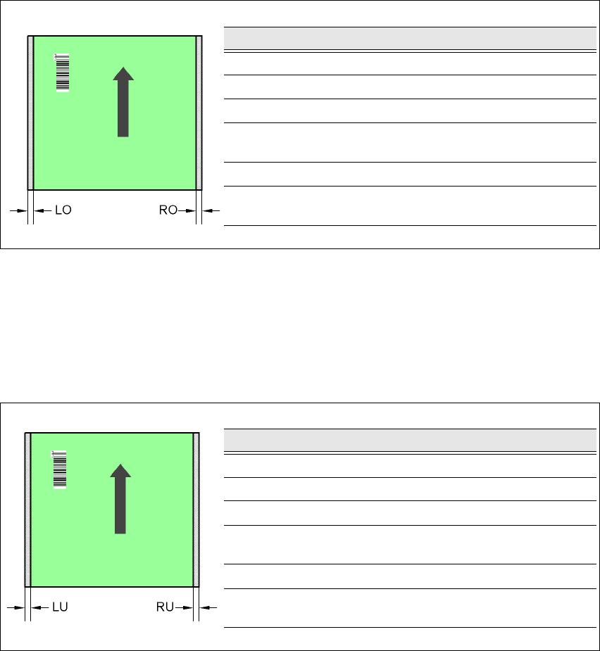
7.5.6.5 Positioning along the width of the PCB -
Scanning beam
along
the direction of travel, PCB barcode reader 1D
up
Fig. 7.5 - 8 Positioning along the width of the PCB - Scanning beam along the direction of travel
PCB barcode reader 1D up
7.5.6.6 Positioning along the width of the PCB -
Scanning beam
along
the direction of travel, PCB barcode reader 1D
down
Fig. 7.5 - 9 Positioning along the width of the PCB - Scanning beam along the direction of travel
PCB barcode reader 1D up
SC Single conveyor
DC1 Dual conveyor, track 1
DC2 Dual conveyor, track 2
SM1 Dual conveyor in single conveyor mode, track 1
SM2 Dual conveyor in single conveyor mode, track 2
PCB dimensions/conveyor LO [mm] RO [mm]
460 mm / SC 3 20
508 mm / SC 3 44
216 mm / DC1 3 24
250 mm / DC1
450 mm / SM1
358
216 mm / DC2 3 3
250 mm / DC2
450 mm / SM2
33
PCB dimensions/conveyor LU [mm] RU [mm]
460 mm / SC 20 3
508 mm / SC 44 3
216 mm / DC1 3 3
250 mm / DC1
450 mm / SM1
33
216 mm / DC2 24 3
250 mm / DC2
450 mm / SM2
58 3
User Manual SIPLACE HF Series 7 Station extensions
Software Version SR.505.xx 05/2004 US Edition 7.6 Ceramic substrate centering
315
7.6 Ceramic substrate centering
7.6.1 General
Ceramic substrates are brittle, and therefore sensitive to the mechanical stresses that can occur
while clamping the PCBs for the placement process, for example. The machine should therefore
always be equipped with mechanical ceramic substrate centering for placing ceramic substrates.
Two mechanical centering devices are installed per conveyor track.
7.6.2 Mechanical centering
The ceramic substrate centering device is fitted to the lifting table. If the substrate has reached its
placement position, the lifting table moves up. When it reaches the top end position, the mechan-
ical ceramic substrate centering device is activated and the substrate is held in place on the PCB
conveyor. The mechanical centering is followed by optical centering with the PCB vision camera.
One particular advantage of ceramic substrate centering is that it allows the ceramic substrate to
be placed right up to the edge.
7 Station extensions User Manual SIPLACE HF Series
7.6 Ceramic substrate centering Software Version SR.505.xx 05/2004 US Edition
316
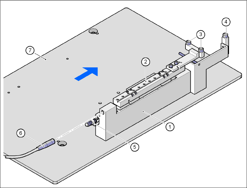
7.6.2.1 Structure
Fig. 7.6 - 1 Structure of the ceramic substrate centering unit
(1) Mechanical ceramic substrate centering
(2) Centering slide
(3) Ball bearing
(4) Stop
(5) Compressed air connection
(6) Proximity switch connecting cable
(7) Lifting table
7
7
7.6.2.2 Preventive maintenance
– Make sure to clean and grease the ball bearings in the X-axis centering unit.
– If necessary, check that the pneumatic driving mechanism is running smoothly.
– The conveyor should be maintained as described in the maintenance instructions.