00193922-01.pdf - 第332页
7 Station extensions User Manual SIPLACE HF Series 7.11 Coplanarity laser module Software Version S R.505.xx 05/2004 US E dition 332 Fig. 7.1 1 - 4 Coplanarity laser module overview (1) Green L ED: 5 operati ng voltage (…

User Manual SIPLACE HF Series 7 Station extensions
Software Version SR.505.xx 05/2004 US Edition 7.11 Coplanarity laser module
331
7.11.4 Overview
7.11.4.1 Analysis unit
The coplanarity laser module consists of two components: the analysis unit with its control sec-
tion, and the laser module. The analysis unit is located in the computer unit (see Fig. 7.11 - 4
).
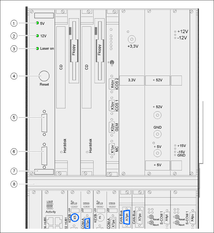
The operating state is indicated by three green LEDs on the front panel of the analysis unit:
Press the RESET key to initialize the coplanarity laser module.
7.11.4.2 Laser module
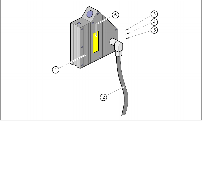
The laser module is fixed to a supporting frame (see Fig. 7.11 - 5).
Two red LEDs and one green LED signal the operating states of the laser module:
LED (see Fig. 7.11 - 4)On Off
1 green 5 operating voltage No voltage
2 green 12V operating voltage No voltage
3 green Laser module in use Laser module switched off
LED (see Fig. 7.11 - 5)On Off
4 red OUT OF RANGE
(outside the measuring range)
–
5 red POOR TARGET
(component is insufficiently reflective)
–
6 green Laser module in use Laser module switched off
7 Station extensions User Manual SIPLACE HF Series
7.11 Coplanarity laser module Software Version SR.505.xx 05/2004 US Edition
332
Fig. 7.11 - 4 Coplanarity laser module overview
(1) Green LED: 5 operating voltage
(2) Green LED: 12V operating voltage
(3) Green LED: laser module switched on
(4) RESET key
(5) SUB-D plug, 9-pin, COM2: to the machine controller
(6) SUB-D plug, 15-pin: to the laser module
(7) Analysis unit with control section
(8) Computer unit
User Manual SIPLACE HF Series 7 Station extensions
Software Version SR.505.xx 05/2004 US Edition 7.11 Coplanarity laser module
333
Fig. 7.11 - 5 Coplanarity module
(1) Laser module
(2) Connecting cable
(3) Red LED:OUT OF RANGE
(4) Red LED:POOR TARGET
(5) Green LED:LASER ON
(6) ’Laser class 3B’ sticker, see Fig. 7.11 - 2