00193922-01.pdf - 第334页
7 Station extensions User Manual SIPLACE HF Series 7.12 SIPLACE pr oductivity lift Software Version S R.505.xx 05/2004 US E dition 334 7.12 SIPLACE productivity lif t 7.12.1 Concept of p arallel plac ement Placeme nt lin…
User Manual SIPLACE HF Series 7 Station extensions
Software Version SR.505.xx 05/2004 US Edition 7.11 Coplanarity laser module
333
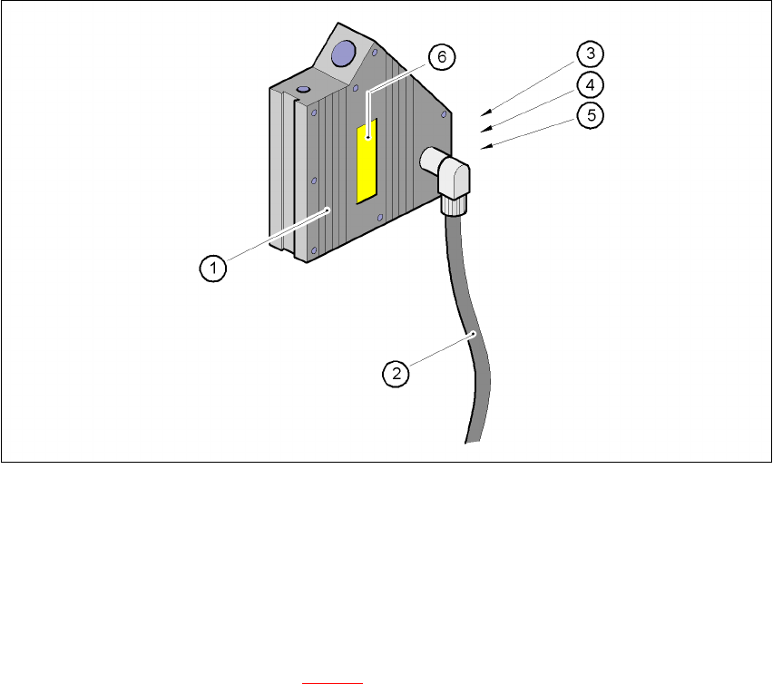
Fig. 7.11 - 5 Coplanarity module
(1) Laser module
(2) Connecting cable
(3) Red LED:OUT OF RANGE
(4) Red LED:POOR TARGET
(5) Green LED:LASER ON
(6) ’Laser class 3B’ sticker, see Fig. 7.11 - 2
7 Station extensions User Manual SIPLACE HF Series
7.12 SIPLACE productivity lift Software Version SR.505.xx 05/2004 US Edition
334
7.12 SIPLACE productivity lift
7.12.1 Concept of parallel placement
Placement lines are generally arranged in series and are linked to one another serially. The
placement program is processed sequentially while the PCBs are transported from one machine
to the next. This means that the placement of a PCB is distributed between various machines.
7
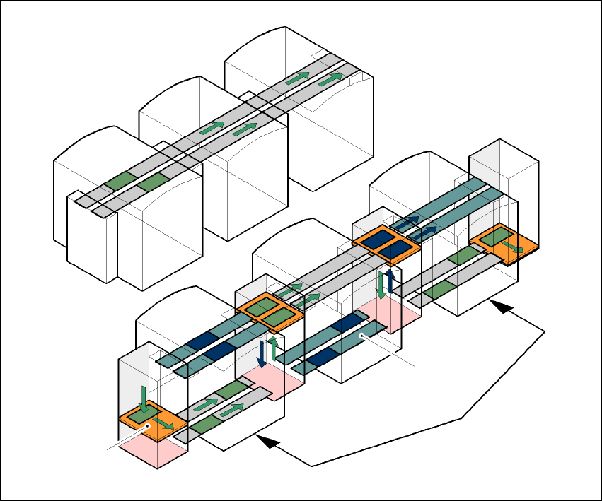
Fig. 7.12 - 1 A comparison of serial and parallel lines
When machines are connected in parallel, the components to be placed by individual machines
are combined. Several machines work through the same placement program. They place all the
components on one machine that would be distributed between several machines with serial pro-
cessing. When one machine runs out of capacity, the PCBs are moved to and placed at the next
machine with the same placement program. This combination of machines with the same com-
ponents to be placed is known as a group or “cluster”.
Serial line
Parallel line
Underfloor conveyor
Group (cluster)
Horizontal/
vertical lift
User Manual SIPLACE HF Series 7 Station extensions
Software Version SR.505.xx 05/2004 US Edition 7.12 SIPLACE productivity lift
335
7.12.2 Implementing parallel placement
Lines with machines arranged in parallel take up a lot more space, so the parallel placement con-
cept was implemented with an underfloor conveyor and horizontal / vertical lift (HV shuttle). The
machines are still arranged in series, but the lift units and underfloor conveyors allow the line to
be operated in parallel. In this way, SIPLACE lines remain almost as compact as before.
Underfloor conveyor
Two conveyor belts carry empty or placed PCBs underneath the machines (see Fig. 7.12 - 1).
Horizontal/vertical lift (horizontal/vertical shuttle)
There is an HV shuttle at the start of a line, between the machines and at the end of the line. It
carries the PCBs between the underfloor and processing levels, and between the two tracks on
the underfloor conveyors.
7
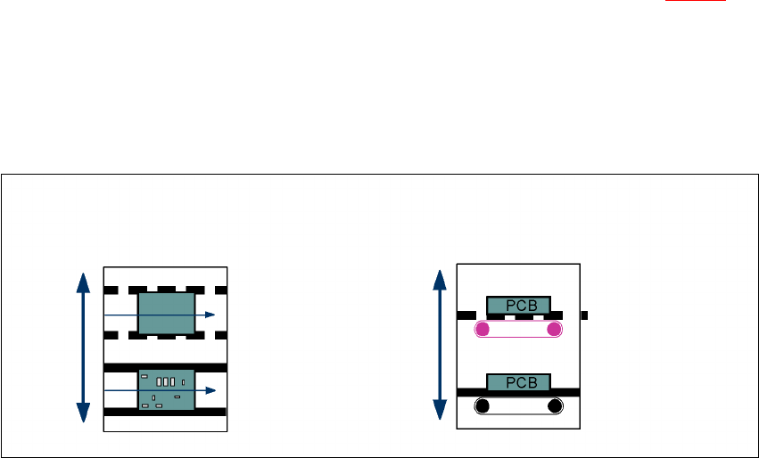
Fig. 7.12 - 2 Horizontal / vertical shuttle (HV shuttle), conveyor track change and lift function
Horizontal conveyor
HV shuttle
Lift function
Vertical conveyor
Unplaced
Placed
Standard
conveyor level
Underfloor
conveyor level
HV shuttle
Conveyor track change