00193922-01.pdf - 第51页
User Manual SIPLAC E HF Series 2 Operational safety Software Vers ion SR.505.xx 05/2004 US Edition 2.5 Safe ty instructions for operating the machine 51 2.5.4 Safety instruct ions for manually moving the Z axis at the T …
2 Operational safety User Manual SIPLACE HF Series
2.5 Safety instructions for operating the machine Software Version SR.505.xx 05/2004 US Edition
50
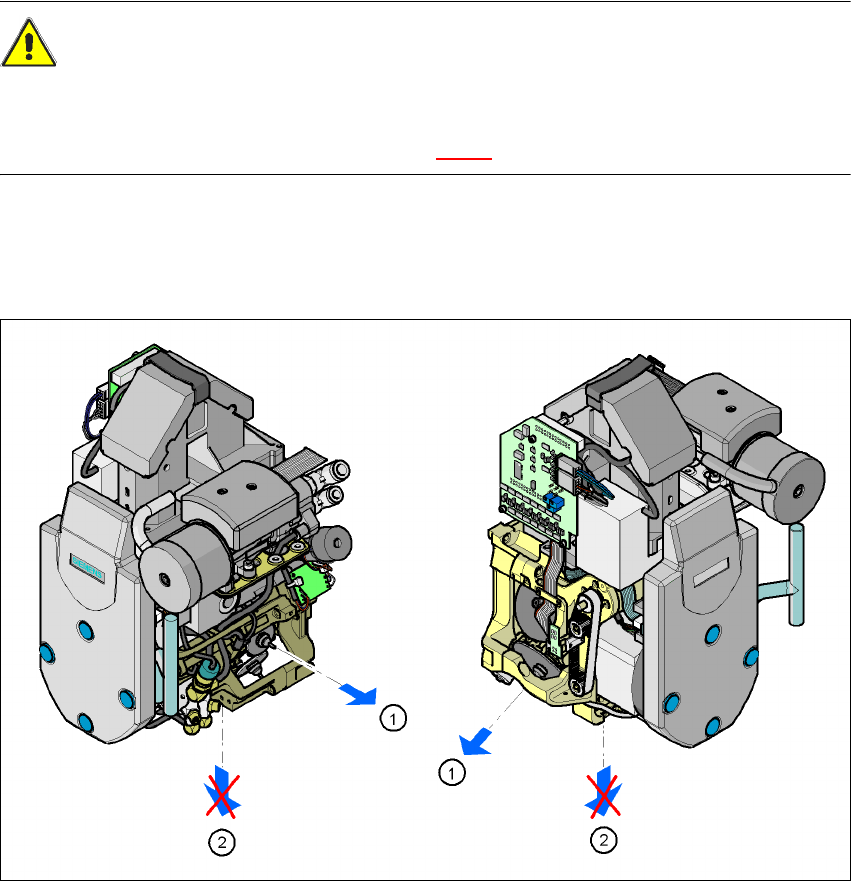
2.5.3 Safety instructions for removing nozzles from Collect&Place heads
CAUTION
RISK OF INJURY TO FINGERS BY SHARP NOZZLES 2
Be careful with your fingers when removing nozzles from their sleeves on Collect&Place heads
at the pick-up / placement position (item 2 in Fig. 2.5 - 2).
The procedure for removing nozzles manually from the sleeve is as follows:
Æ Pace the sleeve from which the nozzle is to be removed to the removal point (item 1).
Æ Remove the nozzle from the sleeve here.
2
Fig. 2.5 - 2 Position of the sleeve during a manual nozzle change
2
(1) Removal position for sleeves and nozzles
(2) Pick-up and placement position
User Manual SIPLACE HF Series 2 Operational safety
Software Version SR.505.xx 05/2004 US Edition 2.5 Safety instructions for operating the machine
51
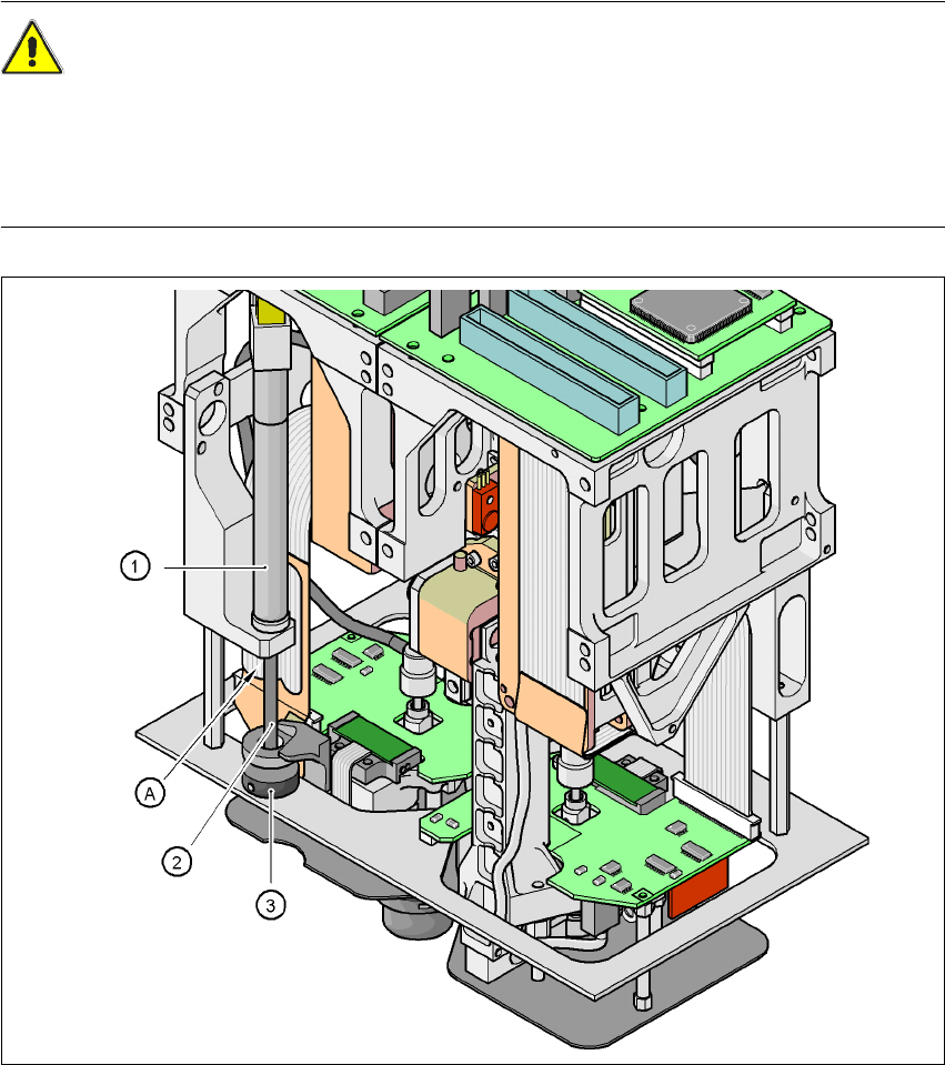
2.5.4 Safety instructions for manually moving the Z axis at the TwinHead
CAUTION
RISK OF CRUSHING AT THE TWINHEAD 2
NEVER move the Z axis down with your hand at the buffer of the return unit. The powerful spring
force of the cylinder creates a risk of injury to your fingers due to the buffer springing back. The
same applies inside the TwinHead when the piston rod springs back into its starting position.
Fig. 2.5 - 3 Risk of crushing from the return unit on the TwinHead
2
(1)Return unit, compressed air cylinder
(2)Piston rod
(3)Buffer of the return unit
(A)Risk of crushing to fingers
2 Operational safety User Manual SIPLACE HF Series
2.5 Safety instructions for operating the machine Software Version SR.505.xx 05/2004 US Edition
52
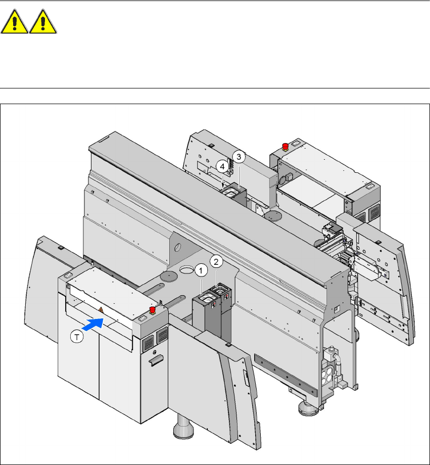
2.5.5 Safety instructions for the TwinHead component cameras during a
placement head change
WARNING 2
When the placement head is changed from the TwinHead to the Collect&Place head, the Twin-
Head's component vision cameras (stationary, P&P, type 22, 50 x 40, and type 20, 8 x 8) must be
removed, otherwise the Collect&Place head will collide with the camera housings.
2
Fig. 2.5 - 4 Safety instructions for the TwinHead vision modules during a placement head change
2
(1) Assembly position, CO camera (stationary, P&P (type 22) 50 x 40), location 1 (HF and HF/3)
(2) Assembly position, CO camera (stationary, P&P (type 20) 8 x 8), location 1 (HF and HF/3)
(3) Assembly position, CO camera (stationary, P&P (type 22) 50 x 40), location 3 (HF)
(4) Assembly position, CO camera (stationary, P&P (type 20) 8 x 8), location 3 (HF)