00193922-01.pdf - 第52页
2 Operational safety User Manual SIPLACE HF Series 2.5 Safety instru ctions for operating the mac hine Software Version SR.505.xx 05/ 2004 US Edition 52 2.5.5 Safety instru ctions for the T winHead component came ras dur…
User Manual SIPLACE HF Series 2 Operational safety
Software Version SR.505.xx 05/2004 US Edition 2.5 Safety instructions for operating the machine
51
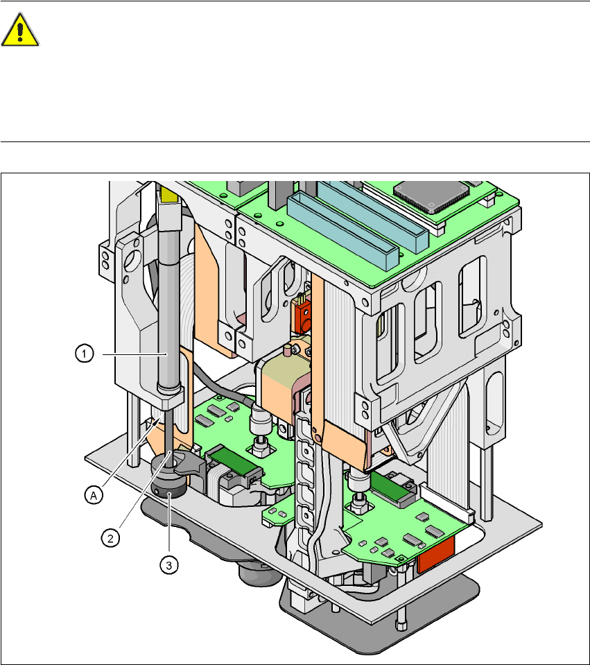
2.5.4 Safety instructions for manually moving the Z axis at the TwinHead
CAUTION
RISK OF CRUSHING AT THE TWINHEAD 2
NEVER move the Z axis down with your hand at the buffer of the return unit. The powerful spring
force of the cylinder creates a risk of injury to your fingers due to the buffer springing back. The
same applies inside the TwinHead when the piston rod springs back into its starting position.
Fig. 2.5 - 3 Risk of crushing from the return unit on the TwinHead
2
(1)Return unit, compressed air cylinder
(2)Piston rod
(3)Buffer of the return unit
(A)Risk of crushing to fingers
2 Operational safety User Manual SIPLACE HF Series
2.5 Safety instructions for operating the machine Software Version SR.505.xx 05/2004 US Edition
52
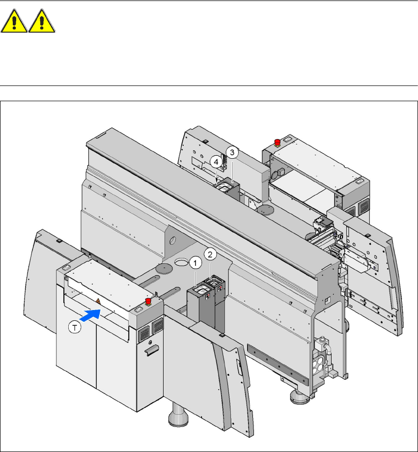
2.5.5 Safety instructions for the TwinHead component cameras during a
placement head change
WARNING 2
When the placement head is changed from the TwinHead to the Collect&Place head, the Twin-
Head's component vision cameras (stationary, P&P, type 22, 50 x 40, and type 20, 8 x 8) must be
removed, otherwise the Collect&Place head will collide with the camera housings.
2
Fig. 2.5 - 4 Safety instructions for the TwinHead vision modules during a placement head change
2
(1) Assembly position, CO camera (stationary, P&P (type 22) 50 x 40), location 1 (HF and HF/3)
(2) Assembly position, CO camera (stationary, P&P (type 20) 8 x 8), location 1 (HF and HF/3)
(3) Assembly position, CO camera (stationary, P&P (type 22) 50 x 40), location 3 (HF)
(4) Assembly position, CO camera (stationary, P&P (type 20) 8 x 8), location 3 (HF)
User Manual SIPLACE HF Series 2 Operational safety
Software Version SR.505.xx 05/2004 US Edition 2.5 Safety instructions for operating the machine
53
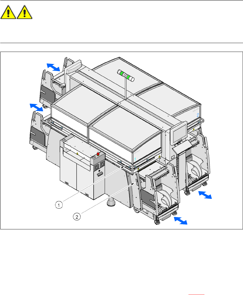
2.5.6 Safety instructions for docking the component trolley in or out
WARNING
To prevent accidents (danger of crushing), only one person may stand in the vicinity of the com-
ponent trolley during docking in and out.
2
Fig. 2.5 - 5 Safety instructions for docking the component trolley in or out
2
(1)Button on top of the hand guard beneath the protective cover
(2)Button, on the side of the hand guard
2
The safety concept for the component trolley change requires the operator to press two buttons
at the same time in order to dock in the component trolley. One button is beneath the protective
cover, while the other is on the side of the hand guard (items 1 and 2 in Fig. 2.5 - 5
). This ensures
that the operator is always standing to the side of the placement machine during docking-in. The
operation always requires the use of both hands, thus preventing the risk of injury to the hands.
Æ Shorten the component tapes on the front end of the feeder to approximately 3 cm before you
dock in the component trolley. The ends of the tape will then slide into the opening in the used