00193922-01.pdf - 第55页
User Manual SIPLAC E HF Series 2 Operational safety Software Vers ion SR.505.xx 05/2004 US Edition 2.6 Safety equipment 55 2.6 Sa fety eq uipme nt 2.6.1 Protectiv e covers 2 Fig. 2.6 - 1 Protective cov ers 2 The traveli …

2 Operational safety User Manual SIPLACE HF Series
2.5 Safety instructions for operating the machine Software Version SR.505.xx 05/2004 US Edition
54
tape channel without manual assistance. This ensures that the operator no longer has to reach
into the danger area of the used tape channel.
2.5.7 Safety instructions for moving the component trolley
WARNING
To prevent accidents, ALWAYS follow the rules listed below when you move the component trol-
ley.
Æ Always hold the handles with both hands when you want to move the component trolley.
Æ Remember that a component trolley with the full complement of feeders can tip over sideways
or forward on gradients of 20° or more.
Æ Make sure that the surface on which the trolley is moved has a significantly smaller gradient.
Æ Be careful not to collide with obstacles. The trolley could tip forward if it is traveling fast enough.
User Manual SIPLACE HF Series 2 Operational safety
Software Version SR.505.xx 05/2004 US Edition 2.6 Safety equipment
55
2.6 Safety equipment
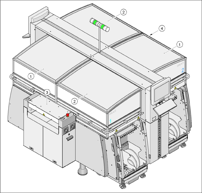
2.6.1 Protective covers
2
Fig. 2.6 - 1 Protective covers
2
The traveling range of the gantries has four protective covers that can be swung upwards. There
are side screens to prevent access to the inside of the machine from the side. Access to the PCB
(1)Protective cover, short
(2)Protective cover, long
(3)Cover and hand guard on the input belt
(4)Cover and hand guard on the output conveyor
2 Operational safety User Manual SIPLACE HF Series
2.6 Safety equipment Software Version SR.505.xx 05/2004 US Edition
56
conveyor is protected by covers, which can be pivoted upwards, over the input and output belts
and hand guards on both belts.
Function 2
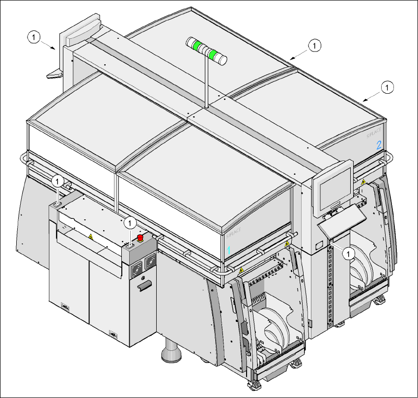
If one of the protective covers has been swung upwards or one of the covers on the PCB conveyor
has been lifted, the power supply to the gantry axes is cut off immediately. The gantry axes stop
moving. The message "Close cover" is displayed on the screen.
Æ Close the protective covers and press one of the Start buttons to continue placement.
2
Fig. 2.6 - 2 Position of the Start button (white) on the machine
(1) Start button (white) on the machine