00193922-01.pdf - 第64页
2 Operational safety User Manual SIPLACE HF Series 2.6 Safety equipment Software Version SR.505.xx 05/2004 US Edition 64 2.6.4 Position of the push-buttons for docking the component trolleys in and out 2 Fig. 2.6 - 7 Pos…
User Manual SIPLACE HF Series 2 Operational safety
Software Version SR.505.xx 05/2004 US Edition 2.6 Safety equipment
63
Protective contactor combination 3TK2806 (item 1 in Fig. 2.6 - 6) 2
The protective contactor combination is contained in the power supply unit. It is used to monitor
the emergency stop circuits and safety equipment.
There are three conditions that must be fulfilled in order to activate the protective contactor com-
bination:
– The "software enable" signal must have been sent.
– The emergency stop loop must be closed.
– The Start button must have been pressed.
On the front panel of the protective contactor combination, there are three green operating display
LEDs (see Fig. 2.6 - 8
, page 65):
– The "Mains" LED indicates that voltage is present.
– The "Channel 1" and "Channel 2" LEDs light up if the Start button was pressed, the emergency
stop loop is closed and the signaling circuit is not signaling a fault status.
Service socket (item 2 in Fig. 2.6 - 6) 2
The service socket is contained in the power supply unit and is protected by the cover. It can only
be used if the placement system is connected to the main power supply via a 5-wire connection
(L1, L2, L3, N, and PE). If a 4-wire connection is used, e.g. without N, the socket cannot be used.
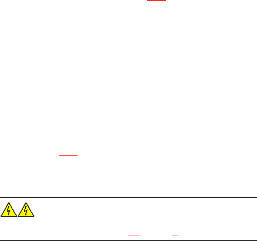
WARNING 2
Always follow the safety instructions concerning potentially lethal voltages - even when the
placement system is switched off. (See Section 2.1.5 from page 26) onwards.
2 Operational safety User Manual SIPLACE HF Series
2.6 Safety equipment Software Version SR.505.xx 05/2004 US Edition
64
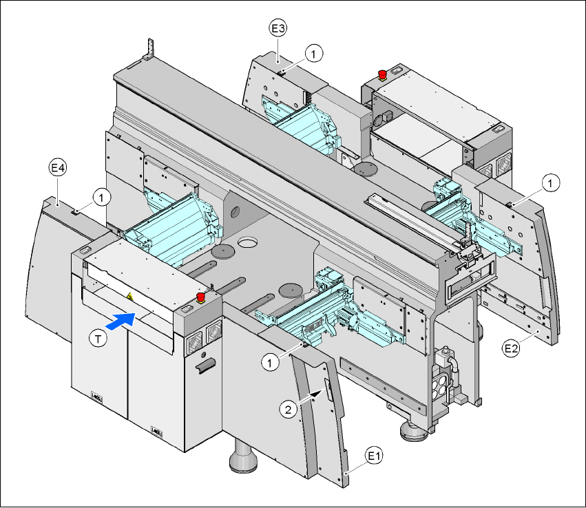
2.6.4 Position of the push-buttons for docking the component trolleys in and out
2
Fig. 2.6 - 7 Position of the push-buttons for docking the component trolleys in and out
2
(1) Push-button on the top
(2) Push-button in the hand guard
E1 Hand guard, location 1
E2 Hand guard, location 2
E3 Hand guard, location 3
E4 Hand guard, location 4
Two push-buttons are integrated into the hand guard module (items E1, E2, E3 and E4). These
are used to dock the component trolley in or out at the location. To
dock out,
press the push-button
(item 1) on the top of the hand guard. To
dock in,
press both push-buttons at the same time (item
1 and item 2). They are far enough apart from one another that you will need both hands to press
the button. This is intended to prevent the risk of injury to operators while docking the component
trolley in or out.
User Manual SIPLACE HF Series 2 Operational safety
Software Version SR.505.xx 05/2004 US Edition 2.6 Safety equipment
65
2.6.5 EMERGENCY STOP loops and signaling circuit
2.6.5.1 Structure of the emergency stop loops
The following contacts are connected in series and form the emergency stop loop:
– make contacts for the four protective cover switches
– make contacts for the two PCB conveyor covers
– make contacts for the two emergency stop buttons
– make contacts for the four component trolleys
– make contacts in the cover flaps (option) over the push-buttons for docking the component trol-
leys in or out.
– Channels of the SSK K6 protective contactor combination
With emergency stop loop 2, the CAN bus signal from the signaling circuit (see Section 2.6.5.2
)
is supplied to channel 2 of the protective contactor combination SSK K6. If the emergency stop
loop is closed, and the signaling circuit is not signaling a malfunction, then the two green LEDs for
channels 1 and 2 light up, in addition to the green mains power check LED of the protective con-
tactor combination.
2
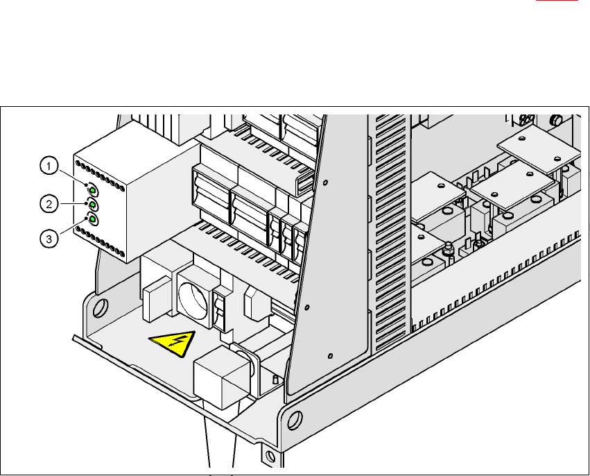
Fig. 2.6 - 8 Signal LED on the protective contactor combination
(1)Netz / Power
(2)Kanal 1 / Channel 1
(3)Kanal 2 / Channel 2