00193922-01.pdf - 第93页
User Manual SIPLAC E HF Series 3 Technical data Software Vers ion SR.505.xx 05/2004 US Edition 3.5 Line conc ept 93 3.5 Line concept 3.5.1 Descri ption 3 The SIPLA CE concept is ch aracteriz ed by its flexi bility, mod u…

3 Technical data User Manual SIPLACE HF Series
3.4 Dimensions and weight of the machines Software Version SR.505.xx 05/2004 US Edition
92
3.4 Dimensions and weight of the machines
3
3
Compressed air supply
Compressed air pressure
p
min
p
max
0.5 MPa = 5.0 bar
1.0 MPa = 10 bar
Compressed air connection
3/4"
Compressed air consumption
with 4 tape cutters and in rela-
tion to the placement head
configuration
HF placement machine
C&P / TH 350 st. l/min
C&P / C&P 450 st. l/min
TH / TH 300 st. l/min
HF/3 placement machine
C&P / C&P / TH 550 st. l/min
C&P / C&P / C&P 700 st. l/min
Operating pressure 0.48 MPa ± 0.025 MPa (4.8 bar ± 0.25 bar)
Compressed air specification
Maximum particle size by density, based on ISO/DIS 8573-1 (class 1)
Particle size 0.1 µm
Particle density 0.1 mg/m³
Maximum oil content (class 1) Particle density 0.01 mg/m³
Pressure dewpoint (class 4) Dewpoint +3°
Noise emissions
Max. noise emissions 74 dB (A)
Permitted environmental factors
Room temperature Between 15°C and 35°C
Atmospheric humidity 30 to 75%
(but no higher than 45% on average in order to prevent any
possibility of condensation on the machine).
Space required (L x W)
HF
HF/3
Weight
HF
HF/3
2380 x 2614 mm² / 6.01 m² (width including monitors)
2380 x 2721 mm² / 6.48 m² (width including monitors)
3800 kg (basic machine)
4700 kg (fully equipped with feeders)
3850 kg (basic machine)
4750 kg (fully equipped with feeders)
User Manual SIPLACE HF Series 3 Technical data
Software Version SR.505.xx 05/2004 US Edition 3.5 Line concept
93
3.5 Line concept
3.5.1 Description
3
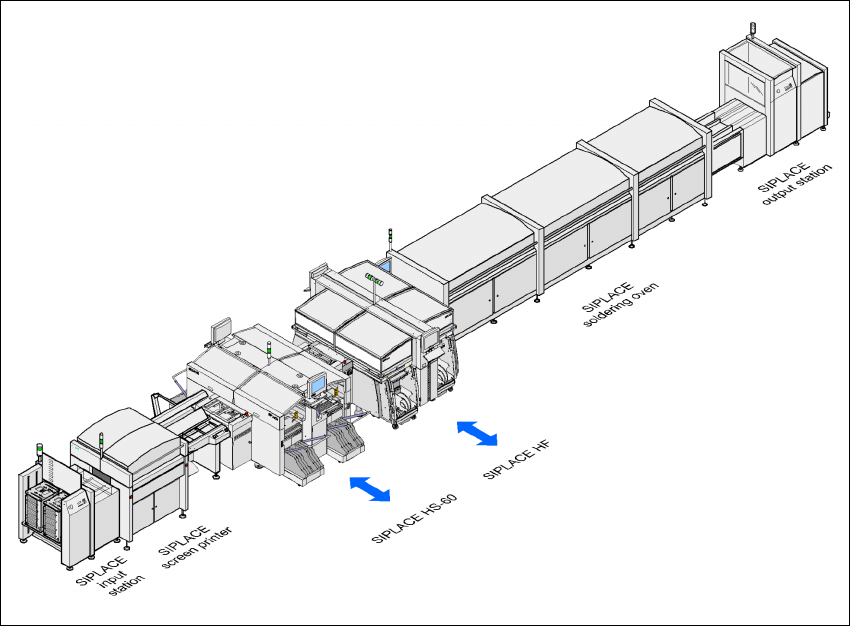
The SIPLACE concept is characterized by its flexibility, modularity, compactness and high power
density. It allows a production line to be individually configured from identical and different mod-
ules. If the production requirements change, the individual placement machines are so compact
that they can be recombined quickly and easily.
3
Fig. 3.5 - 1 Sample line concept
3
The SIPLACE family has exactly the right placement machine, whatever the output requirements:
SIPLACE HF and HF/3 placement machines can be used to place IC, flip-chip, bare die and ex-
otic components (OSC). They cover the spectrum of components from 0201 to 85 x 85 / 125 x 10
mm² with a high placement rate.
The SIPLACE HS-60 is a super high-speed placement machine for processing components rang-
ing from 0201 through to 18.7 x 18.7 mm².
The SIPLACE S-27 HM is a high-speed system for placing components from 0201 to 32 x 32 mm².

3 Technical data User Manual SIPLACE HF Series
3.5 Line concept Software Version SR.505.xx 05/2004 US Edition
94
The SIPLACE F5 HM high-speed system places large ICs, flip-chips, bare dies and exotic com-
ponents (OSC). The component sizes range from 0201 to 55 x 55 mm²
The SIPLACE set-up optimization increases the productivity of your line since it minimizes place-
ment times and non-productive times for your placement machines. The set-up software calcu-
lates individual set-ups for individual products, individual set-ups for different products and family
set-ups for different products. The program data can be exchanged between the individual lines -
even for different machine configurations.
3.5.2 Technical data
System SIPLACE SMD placement lines
Placement modules SIPLACE HS-60, SIPLACE S-27 HM, SIPLACE HF, HF/3, F5
HM
Peripheral modules Input/output stations, screen printers, soldering ovens,
inspection stations, etc., available from SIEMENS L&A
Range of components 0201 to 85 x 85 mm² / 125 x 10 mm²
up to 200 x 125 mm² (with restrictions)
PCB conveyor Single and dual conveyor with automatic width adjustment
unit
Placement rate Depends how modules are connected in series
Space required 4 m² per S module
6 m² per HF module
6.5 m² per HF/3 module
7.5 m² per HS module