00193922-01.pdf - 第95页
User Manual SIPLAC E HF Series 3 Technical data Software Vers ion SR.505.xx 05/2004 US Edition 3.6 Placem ent heads 95 3.6 Placement heads 3.6.1 Head modularity One par ticular ad vantag e of the SIP LACE HF series i s i…

3 Technical data User Manual SIPLACE HF Series
3.5 Line concept Software Version SR.505.xx 05/2004 US Edition
94
The SIPLACE F5 HM high-speed system places large ICs, flip-chips, bare dies and exotic com-
ponents (OSC). The component sizes range from 0201 to 55 x 55 mm²
The SIPLACE set-up optimization increases the productivity of your line since it minimizes place-
ment times and non-productive times for your placement machines. The set-up software calcu-
lates individual set-ups for individual products, individual set-ups for different products and family
set-ups for different products. The program data can be exchanged between the individual lines -
even for different machine configurations.
3.5.2 Technical data
System SIPLACE SMD placement lines
Placement modules SIPLACE HS-60, SIPLACE S-27 HM, SIPLACE HF, HF/3, F5
HM
Peripheral modules Input/output stations, screen printers, soldering ovens,
inspection stations, etc., available from SIEMENS L&A
Range of components 0201 to 85 x 85 mm² / 125 x 10 mm²
up to 200 x 125 mm² (with restrictions)
PCB conveyor Single and dual conveyor with automatic width adjustment
unit
Placement rate Depends how modules are connected in series
Space required 4 m² per S module
6 m² per HF module
6.5 m² per HF/3 module
7.5 m² per HS module
User Manual SIPLACE HF Series 3 Technical data
Software Version SR.505.xx 05/2004 US Edition 3.6 Placement heads
95
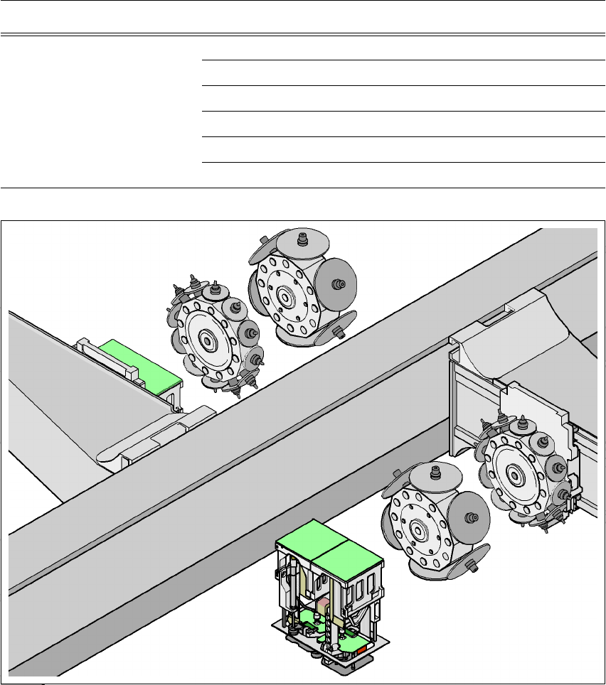
3.6 Placement heads
3.6.1 Head modularity
One particular advantage of the SIPLACE HF series is its head modularity. For example, the
placement heads on the gantries can be quickly changed and adapted to the placement require-
ments.
3.6.1.1 Placement head configuration on the HF placement machine
3
3
Fig. 3.6 - 1 Head modularity - SIPLACE HF
Placement area 1, gantry 1 Placement area 2, gantry 3
Placement head C&P12 C&P12
C&P12 C&P6
C&P12 TH
C&P6 C&P6
C&P6 TH
TH TH
Gantry 3
Gantry 1
TH
C&P12
C&P6
C&P12
C&P6
TH
Placement area 2
Placement area 1
3 Technical data User Manual SIPLACE HF Series
3.6 Placement heads Software Version SR.505.xx 05/2004 US Edition
96
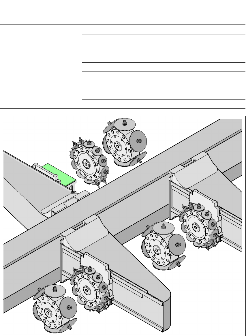
3.6.1.2 Placement head configuration on the HF/3 placement machine
3
Fig. 3.6 - 2 Head modularity - SIPLACE HF/3
3
Placement area 1 Placement area 2
Gantry 1 Gantry 4 Gantry 3
Placement head C&P12 C&P12 C&P12
C&P12 C&P12 C&P6
C&P12 C&P12 TH
C&P12 C&P6 C&P6
C&P12 C&P6 TH
C&P6 C&P12 C&P6
C&P6 C&P12 TH
C&P6 C&P6 C&P6
C&P6 C&P6 TH
Gantry 3
Gantry 1
TH
Gantry 4
C&P12
C&P6
C&P6
C&P12
C&P12
C&P6
Placement area 2
Placement area 1