00197551-01_MM_CPP-CP-Twin_Kunde_en.pdf - 第12页
Introduction Staff Qualifications and Training 1.3.6 SIPLACE on the World Wid e Web (WWW) 12 Maintenance Manual SIPLACE Placement Heads CPP, C&P20, Twin 1.3.6 1 . 3 . 6 S I P L A C E o n t h e W o r ld W id e W e b (…

Introduction
1.3.4 Validity of Document Other Instructions
Maintenance Manual SIPLACE Placement Heads CPP, C&P20, Twin 11
Always place the modules on a conductive surface (table with an ESD coating, conductive ESD foam,
ESD bag or container).
Do not bring modules near visual display units, monitors or televisions. Keep them at least 10 cm away
from the screen.
1.3.3.4
1.3.3.4 Measurements and Modifications to ESD Modules
Measurements and Modifications to ESD Modules
Measurements of the assemblies may only be taken if
▪ The measuring device has been grounded (e.g. via protective conductor) or
▪ The measuring head of the potential-free measuring device has been briefly discharged before
measurement (e.g. touching blank metal control unit housing).
► Always use an earthed soldering iron if you carry out any soldering work.
1.3.3.5
1.3.3.5 Dispatching ESD Modules
Dispatching ESD Modules
► Always store modules and components in conductive packaging (e.g. metallized plastic bags or met-
al sleeves) and dispatch them in conductive packaging.
► If the packaging is not conductive, place the modules in a conductive envelope before packaging.
Use conductive foam rubber, ESD bags, domestic aluminum foil or paper, for example. NEVER use
plastic bags or film.
► If the module has integral batteries, ensure that the conductive packaging does not touch or short-
circuit the battery terminals and, if necessary, first cover the terminals with insulating tape or mate-
rial.
1.3.4
1.3.4 Validity of Document
Validity of Document
This document contains maintenance work instructions for all SIPLACE placement heads of type
C&P20, CPP, and Twin.
▪ If the work required should differ from the standard procedure, this will be indicated with reference
to the version and delivery state.
▪ Diagrams should be seen as examples e.g. a different paint finish does not mean that the following
information only applies to the type shown.
1.3.5
1.3.5 Release History
Release History
Document
SIPLACE placement heads CPP, C&P, Twin
Maintenance Manual
Release Changes
06/2014 First edition
Introduction
Staff Qualifications and Training 1.3.6 SIPLACE on the World Wide Web (WWW)
12 Maintenance Manual SIPLACE Placement Heads CPP, C&P20, Twin
1.3.6
1.3.6 SIPLACE on the World Wide Web (WWW)
SIPLACE on the World Wide Web (WWW)
Log into our SIPLACE
®
homepage at http://www.siplace.com.
► You can choose between the German and English versions.
The different sections contain information about our products, services and contact persons.
In addition, registered customers can also access the
SIPLACE User Group
. Here you can call up spe-
cial information about our placement systems e.g.
▪ Technical documentation,
▪ Technical information,
▪ Spare parts lists etc.
Registration for the user group is very simple:
► Click on the Register link.
► Fill in the registration form and send it off to us.
Soon afterwards, you will receive your access authorization with USER ID and password.
1.4
1.4 Staff Qualifications and Training
Staff Qualifications and Training
Qualified or adequately trained personnel means that these people are familiar with the setting up, op-
eration and maintenance of automatic placement systems and add-on devices and are suitably qualified,
e.g.:
▪ Have been trained, instructed or authorized to switch on and off, isolate, earth and identify electrical
circuits and system components in accordance with normal safety standards.
▪ Have been trained or instructed in the upkeep and use of appropriate safety equipment in accord-
ance with normal safety standards.
▪ Have received first aid training.
Overview of the Modules
CPP
Maintenance Manual SIPLACE Placement Heads CPP, C&P20, Twin 13
2
2 Overview of the Modules
Overview of the Modules
2.1
2.1 CPP
CPP
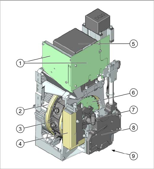
CPP
CPP with camera SST29 [03070108-xx]
CPP without camera [03053528-xx]
1. Intermediate distributor 1 and 2 (ID1, ID2)
2. Star motor (integrated in head housing)
3. DP axis (as direct drive)
4. Pressure control valve
5. Component camera (behind the intermediate distrib-
utor, standard: SST29)
6. Single core solution (SCS) – DP drive control
7. Holding circuit supply, integrated venturi nozzles and
valve assembly (valve terminal)
8. Z axis with return cylinder
9. Component sensor in the pick and place position (on
the underside)