00197551-01_MM_CPP-CP-Twin_Kunde_en.pdf - 第26页
Maintenance tasks for CPP Performing Maintenance Tasks 3.5.2 Maintenance Tasks on Vacuum-Conducting Parts 26 Maintenance Manual SIPLACE Placement Heads CPP, C&P20, Twin Replacing the O-Rings on the Housing of the Hol…
Maintenance tasks for CPP
3.5.2 Maintenance Tasks on Vacuum-Conducting Parts Performing Maintenance Tasks
Maintenance Manual SIPLACE Placement Heads CPP, C&P20, Twin 25
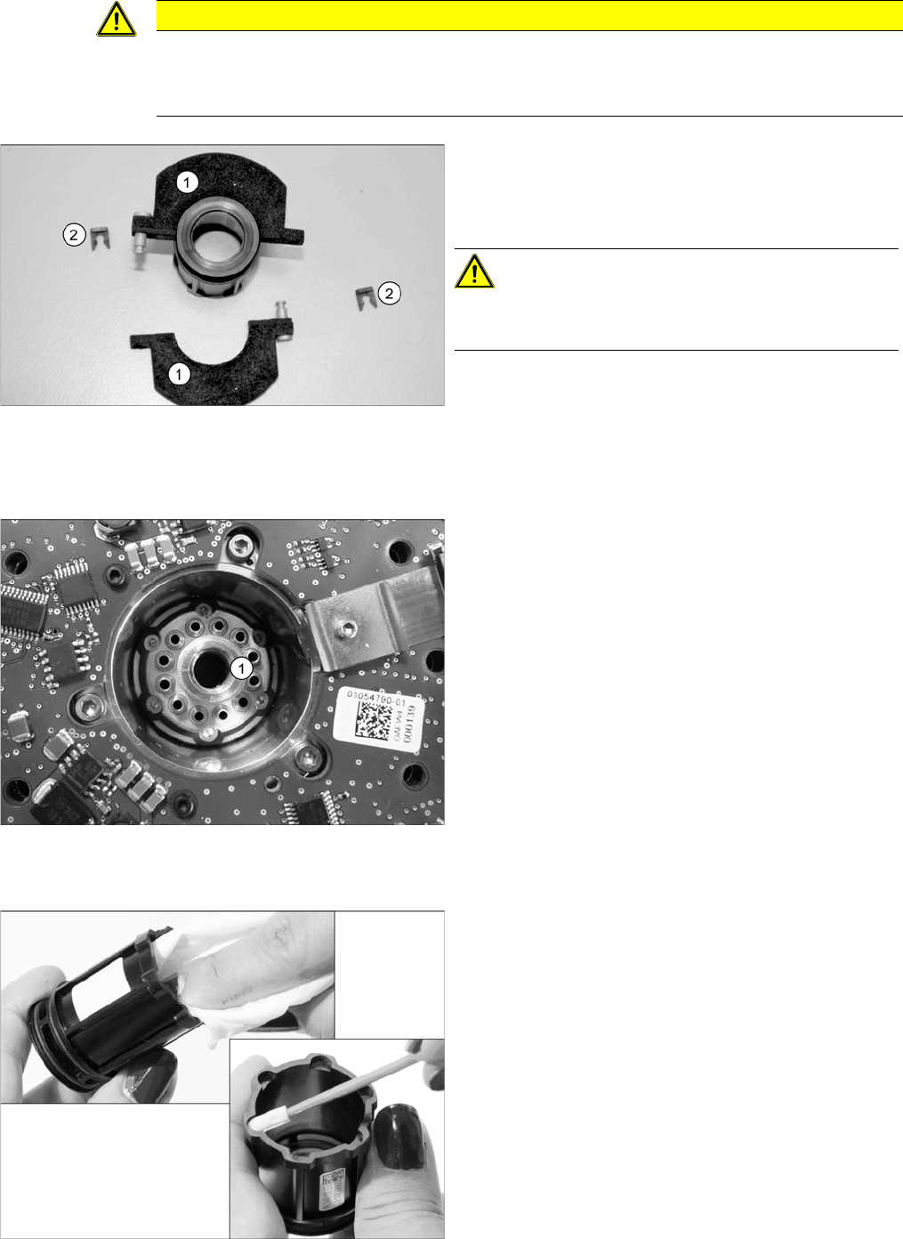
Checking/Replacing the Silencer
Removing the Holding Circuit
Cleaning the Housing of the Holding Circuit
CAUTION
Damage of the board
When replacing the silencer, the board located beneath it could be damaged.
► Only replace the silencer on the removed holding circuit housing.
► Carefully remove the two retaining clips (2) on the left
and right of the silencer (1). You will need to support
the tab on the silencer with your fingers. This pre-
vents the tab from breaking off.
CAUTION!
Make sure that you do not bend the silencer!
Always open both retaining clips to remove the silencer!
► Remove the silencer.
► Check the silencer for dirt and damage. Replace the
silencer, if required.
► Dismantle the holding circuit (1). This task must be
carried out by authorized personnel. For removal and
installation details, read the Service manual.
► Use a cloth and cleaning stick to clean the cover, in-
cluding all grooves and recesses.
You can also use an anti-static plastic cleaner for bet-
ter cleaning results.
Maintenance tasks for CPP
Performing Maintenance Tasks 3.5.2 Maintenance Tasks on Vacuum-Conducting Parts
26 Maintenance Manual SIPLACE Placement Heads CPP, C&P20, Twin
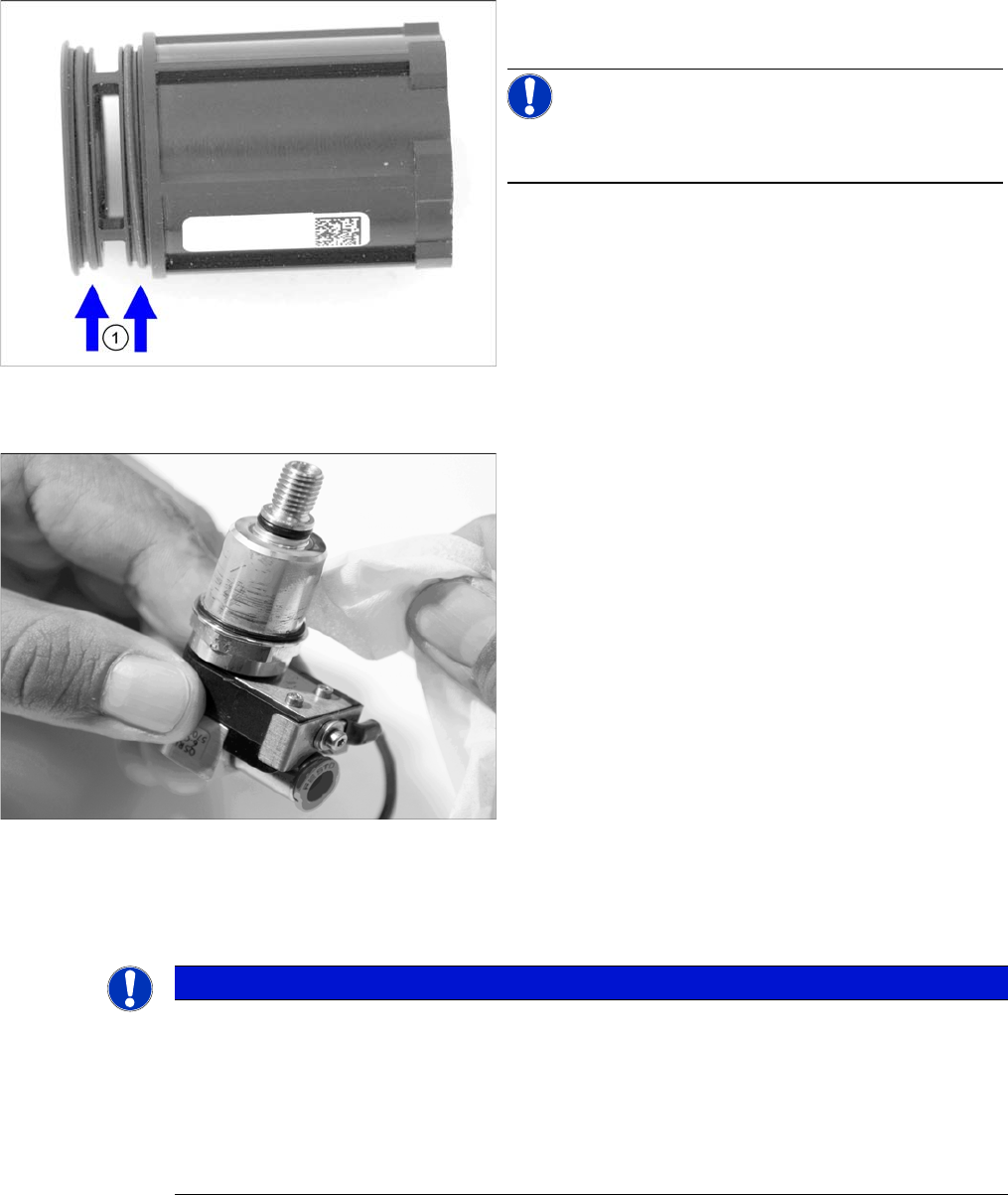
Replacing the O-Rings on the Housing of the Holding Circuit
Cleaning the Screwed Joint
Installing the Silencer and the Screwed Joint
► Fit a new/cleaned holding circuit. This task must be carried out by authorized personnel. For removal
and installation details, read the Service manual.
► Fit the silencer and the screwed joint. This task must be carried out by authorized personnel. For
removal and installation details, read the Service manual.
► Replace the O-rings on the housing of the holding cir-
cuit
NOTICE!
The O-rings are contained in the set of seals for the hold
circuit [03095007-xx].
► Clean the screwed joint with a lint-free cleaning cloth.
You can also use an anti-static plastic cleaner for bet-
ter cleaning results.
NOTICE
Recommendations for installing the holding circuit
► We recommend that you have an additional holding circuit available, so that this can be
easily replaced during head maintenance.
The actual cleaning of the removed holding circuit can be performed later on (see "7.3.1
CPP: Cleaning/Checking the Holding Circuit" [ ➙ 76]).
► Replace all seals when installing the holding circuit.
The seals are contained in the set of seals for the hold circuit [03095007-xx].
Maintenance tasks for CPP
3.5.3 Oiling the Z-Axis Support Roller (Version 05 Only) Performing Maintenance Tasks
Maintenance Manual SIPLACE Placement Heads CPP, C&P20, Twin 27
3.5.3
3.5.3 Oiling the Z-Axis Support Roller (Version 05 Only)
Oiling the Z-Axis Support Roller (Version 05 Only)
► For this maintenance task, use the yellow combitip with Klüber oil GEM 1 220 N.
► Set the multipette to 1 µl.
3.5.4
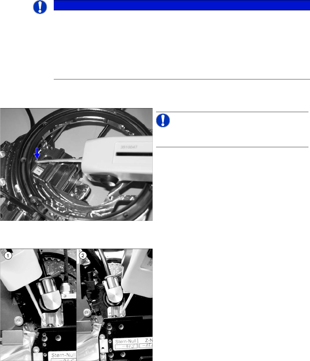
3.5.4 Oiling the Z Axis Linear Guidance
Oiling the Z Axis Linear Guidance
NOTICE
This maintenance task may not always be needed. This depends on the placement head ver-
sion being used.
As part of the product enhancement process, different methods of lubricating the CPP support
roller have been used:
► CPP versions without service hole to oil the support roller have a maintenance-free bearing
and do not require any additional oiling.
► CPP versions with a service hole to oil the support roller and yellow mark are to be oiled as
follows.
NOTICE!
Lubricate via the service hole n the back of the front plate.
The front plate needs to be removed for this.
► Press the Z axis up to the top stop. This gives you ac-
cess to the service hole.
► Insert the multipette into the service hole and apply
1 µl of lubricant to the supporting roller.
► Move the Z axis manually in and out approx. five
times.
► Clean the linear guide with a cleaning stick.
► For this maintenance task, use the blue combitip with
Thermoplex ALN 1001/00.
► Set the multipette to 4 µl.
► Position the multipette at the center of the left (1)
guide track side.
Apply 4 µl of lubricant.
Now move the multipette slightly upwards to distrib-
ute the droplet.
Do the same on the right side (2) of the guide track.
► Move the Z axis manually in and out approx. five
times.
► Using the same method, apply another 4 µl in each
case and move the Z-axis another five times.
⇨ A total of 8 µl must be applied to each guide track (=
two times 4 µl).