ServiceInstruction_Vision XP - 第100页
Page 96 Vision XP+ V AC 3 Setup Instructions 3.8 Consumption Parameter Operating Instructions V ersion 1.5 3.8 Consump tion Para meter Fig. 3-1 3 Consu mption P arameter A) Converter rati o Converter rati o of the energy…

Vision XP+ VAC Page 95
3 Setup Instructions
3.7 N2 Operating Parameters
Operating Instructions
Version 1.5
H) Kp
Proportional component for the PID controller.
I) Tn
Integral component for the PID controller.
J) Tv
Differential component for the PID controller.
K) Type
Reserved for special applications.
L) Application
Reserved for special applications.
M) Offset
Deviation at the residual oxygen display can be compensated for with the
offset function.
N) Hysteresis
Tolerance evaluation performance can be adapted with the hysteresis
function.
O) Base Level Factor
• If the basic level factor is 0, the basic valve is actuated just like the
control valve.
• If the basic level factor lies within a range of 1 to 223, the basic valve
is coupled to the control valve via a filter function. Time „ta“ plays a
role in this respect. The duration of time during which filtering takes
place is calculated with the following formula
tf = ta x 100 ms x basic level factor
Example: ta = 20, basic level factor = 6 (time for mean value
generation)
tf = 20 x 100 ms x 6 = 12s
• If the basic level factor is 224 with a 6 bar valve or
if the basic level factor is 327 with a 2 bar valve,
the basic valve is actuated directly by means of the basic level.
• The entry under Base Level in the menu Masks is scaled with this
factor (submenu for N2 operating mode, see chapter 5.5.10 in the
operating instructions).
Page 96 Vision XP+ VAC
3 Setup Instructions
3.8 Consumption Parameter
Operating Instructions
Version 1.5
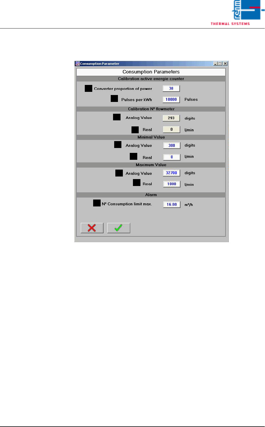
3.8 Consumption Parameter
Fig. 3-13 Consumption Parameter
A) Converter ratio
Converter ratio of the energy meter.
B) Pulses per kWh
Number of pulses of the energy meter per kilowatt-hour.
When using the active energy counter (Gossen-Metrawatt), set for
10.000 pulses per kWh.
When using the active energy counter (B+R for VXP+), set for 0 pulses
per kWh.
C) Analog value
Indication of analog value of the input.
D) Real
Real value corresponding to the analog value.
E) Analog value minimum value
Analog value corresponding to real minimum value.
F) Real minimum value
Real value corresponding to the analog minimum value.
G) Analog value maximum value
Analog value corresponding to the real maximum value.
A
B
C
D
E
F
G
H
I
Vision XP+ VAC Page 97
3 Setup Instructions
3.9 Filter F9 Parameter
Operating Instructions
Version 1.5
H) Real maximum value
Real value corresponding to the analog maximum value.
I) N2 consumption limit value
N2 consumption from which a warning is indicated due too high con-
sumption.
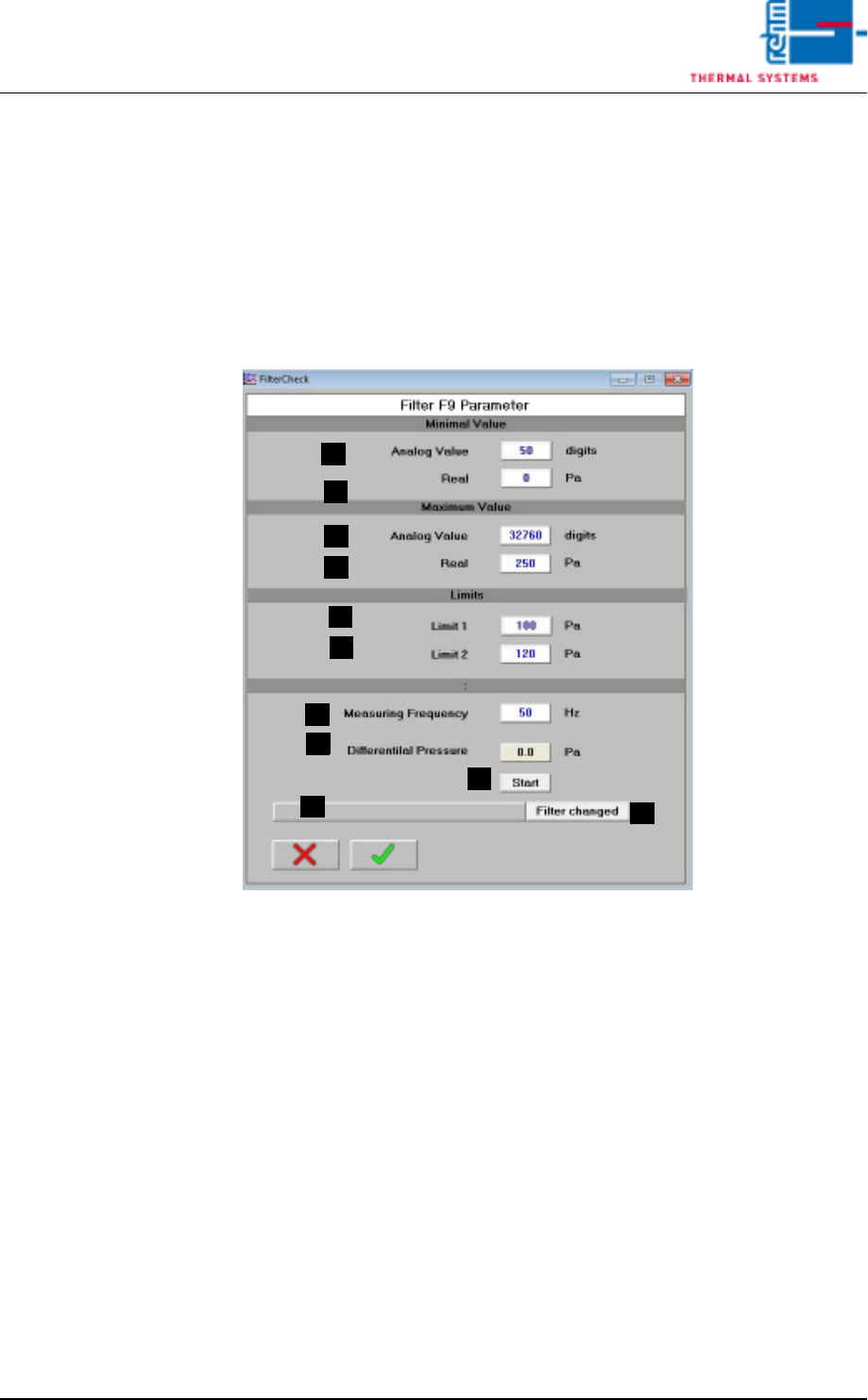
3.9 Filter F9 Parameter
A) Analog Value Minimum Value
Analog Value, which matches the Real Minimum Value.
B) Real Minimum Value
Real Value, which matches the Analog Minimum Value.
C) Analog Value Maximum Value
Analog Value, which matches the Real Maximum Value.
D) Real Maximum Value
Real Value, which matches the Analog Maximum Value.
E) Limit Value 1
Differential pressure for warning message
F) Limit Value 2
Differential pressure for message with the demand of filter change.
G) Test frequency
Frequency for the frequency converter of the cooling section during the
measurement for the filter checking.
H) Differential pressure
Current differential pressure at the filter.
A
B
C
D
E
F
G
H
I
J
K