ServiceInstruction_Vision XP - 第107页
Vision XP+ V AC Page 103 3 Setup Instructions 3.13 Settings for Individual Components Operating Instructions V ersion 1.5 3.13 Settings for Indi vidual Com ponent s 3.13.1 Adjustment instruction for the vacuum pump posit…
Page 102 Vision XP+ VAC
3 Setup Instructions
3.12 Vacuum parameters
Operating Instructions
Version 1.5
3.12 Vacuum parameters
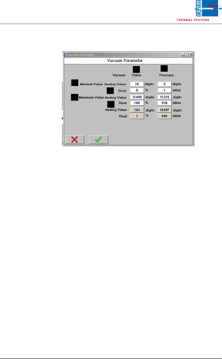
Fig. 3-16 Vacuum parameters
These settings are set during commissioning by the service engineer of the
company Rehm Thermal Systems GmbH.
A) Analogue value
Raw value.
B) Real
Negative pressure.
C) Valve
Adjustment values for the regulating valve.
D) Pressure
Adjustment values for the pressure.
A
A
B
B
D
C
Vision XP+ VAC Page 103
3 Setup Instructions
3.13 Settings for Individual Components
Operating Instructions
Version 1.5
3.13 Settings for Individual Components
3.13.1 Adjustment instruction for the vacuum pump positioner
The positioner may be set and operated on the process and adjustments
level
Process level:
The running process will be shown and controlled on the process level.
Operating mode
– AUTOMATIC -Process data display
– MANU - Manual opening and closing of the valve.
Adjustment level:
Basic process settings may be made on the adjustment level.
– Entering the operating parameters
– Activation of additional functions.
Note!
If the apparatus is in AUTOMATIC mode when switching to the adjustment
level, the process will continue running during adjustments.
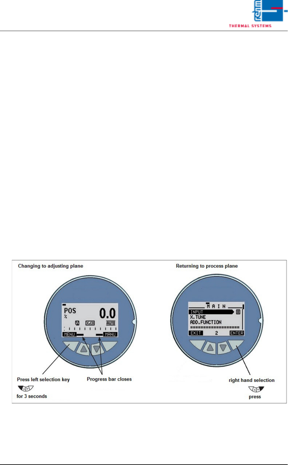
Fig. 3-17 Changing to adjusting plane
Press menu key for 3 seconds; the main menu opens.
The “INPUT” menu item is displayed. Press “ENTER” to confirm.

Page 104 Vision XP+ VAC
3 Setup Instructions
3.13 Settings for Individual Components
Operating Instructions
Version 1.5
Select “0-10 V” input signal
(the function is marked with “ “) and confirm with “SELEC“.
Exit the submenu by pressing “EXIT”.
Note!
The additional functions are activated via the basic function
"ADD.FUNCTION” and then taken over in the main menu (MAIN).
Now use the arrow key to page down in the menu until the submenu “ADD
FUNCTION” appears and confirm with “ENTER”.
Then select the analog output (Position 21) “OUTPUT” (the function is
marked with “X”) and confirm with “ENTER”.
Continue to the current as-is position (Position 26), select “POS-Sensor” and
confirm with “ENTER”.
Exit the submenu by pressing “EXIT”.
Select submenu “OUTPUT” and confirm with “ENTER”.
Select submenu “ANALOG” and confirm with “ENTER”.
Select POS (the function is marked with “ “) and confirm with “SELEC“.
Using the arrow page down and select “OUTtype”, confirm with “ENTER”.
Select subitem “0 – 10 V” and confirm with “SELEC”.
Press “EXIT” 4 times to return to the main menu.