ServiceInstruction_Vision XP - 第114页
Page 1 10 Vision XP+ V AC 3 Setup Instructions 3.15 Configuration Activ Energy Meters Operating Instructions V ersion 1.5 B) Changing pa rameter values 1. Briefly press the enable key first, as described under Item a) (a…
Vision XP+ VAC Page 109
3 Setup Instructions
3.15 Configuration Activ Energy Meters
Operating Instructions
Version 1.5
3.15 Configuration Activ Energy Meters
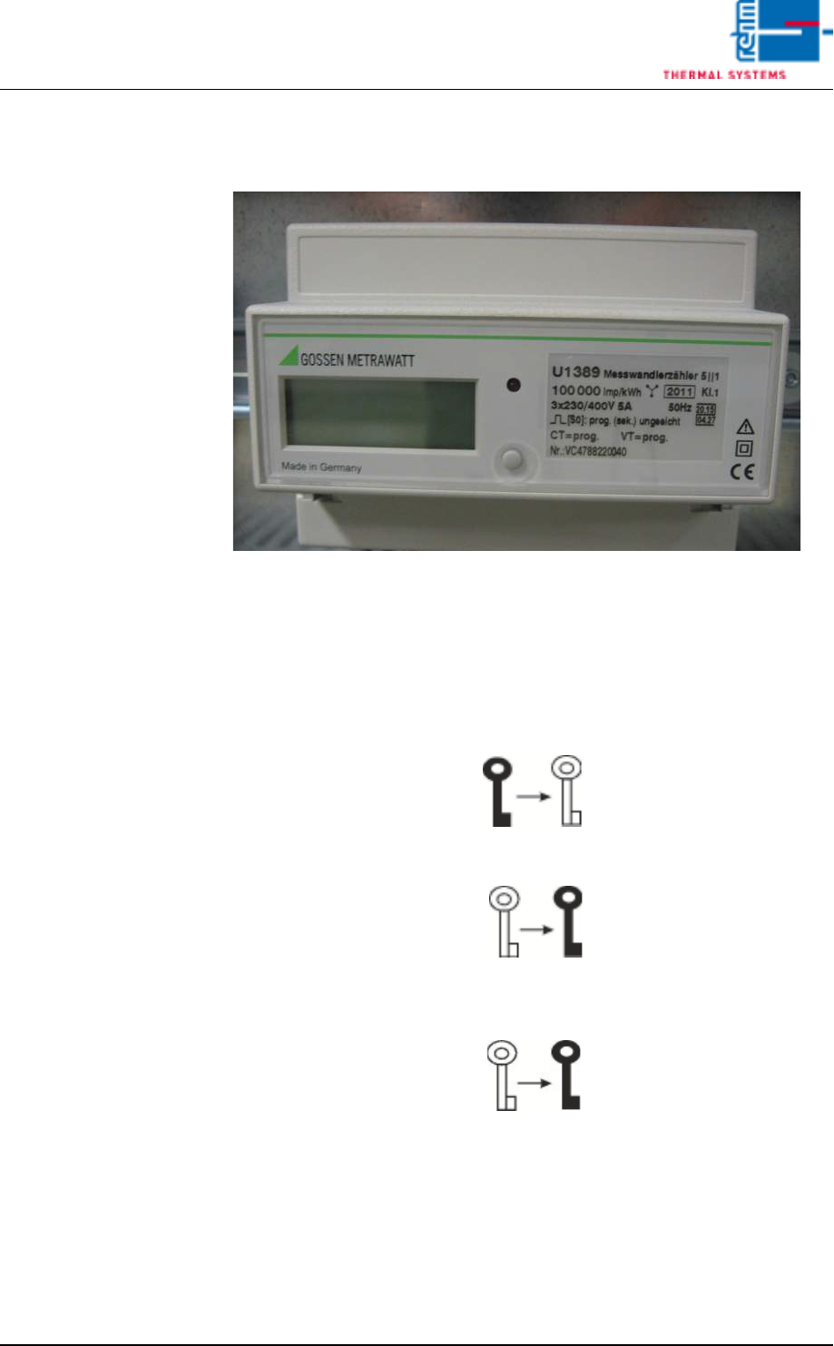
Fig. 3-22 Configuration Activ Energy Meters
A) Enabling parameter modifications
• The enable key serves to enable or disable parameter changes. It is locat-
ed below the terminal cover and is activated with a pointed object (e. g.
ballpen).
• Pressing the key for the first time activates operating mode „Change pa-
rameters“ (key off):
• Renewed activation disables operating mode „Change parameters“
(key on):
• If the key is not activated for approx. 2 minutes, operating mode „Change
parameters“ is automatically aborted and blocked. The key is displayed
again:

Page 110 Vision XP+ VAC
3 Setup Instructions
3.15 Configuration Activ Energy Meters
Operating Instructions
Version 1.5
B) Changing parameter values
1. Briefly press the enable key first, as described under Item a) (activates
operating mode „Change parameters“).
2. Press and hold the menu key once until the read-out test is displayed.
3. Repeatedly press the menu key until the parameter to be changed ap-
pears at the display.
4. Press and hold the menu key until the parameter value at the digit with
the highest value (on the far left-hand side) blinks.
• Example - Parameters:
CT = 150/5A 30
Pulse rate: 10000 Pulses/kWH
Vt = 1
5. Please wait until the point which is to be changed is flashing (e. G. ten).
Then press three times, the desired value 30 appears. Please wait again
until the flashing cycle is finished. Now, the value 30 is accepted.
6. By short pressing the Menu button you will reach the next parameter lev-
el.
7. This parameter will be fixed as described under point 5.
8. Press the menu key several times until the standard display appears.
9. Press the enable key once more. This disables operating mode
„Change parameter values“.

Vision XP+ VAC Page 111
3 Setup Instructions
3.16 Adjustment, Inspection
Operating Instructions
Version 1.5
3.16 Adjustment, Inspection
3.16.1 Inspecting Conveyor Width for Parallelism
Procedure:
1. Discharge all PCBs from the system. The conveyor must be completely
empty of PCBs.
2. Set conveyor width to 200 mm in the main window.
3. Open the process chamber with the software button.
4. After the conveyor has automatically adjusted its width to 200 mm, set
the 200 x 300 mm sheet metal panel onto the conveyor at the inlet. The
gap between the conveyor and the panel should not exceed 1 mm. If the
gap is larger than 1 mm, the conveyor must be manually readjusted to
match the width of the sheet metal panel, and conveyor width must be
calibrated after double checking (see chapter 3.3.3 Chain Lubricator, on
page 73).
5. Slowly push the sheet metal panel through the system, and continuously
check the size of the gap at the stations. If fluctuations of greater than
2 mm are detected, the conveyor must be mechanically adjusted.
6. Remove the sheet metal panel from the outlet. If conveyor width is within
tolerance, and if uniform parallelism prevails over the entire length of the
conveyor, work can now be continued.