ServiceInstruction_Vision XP - 第122页
Page 1 18 Vision XP+ V AC 3 Setup Instructions 3.18 Exhaust Air Monitoring Operating Instructions V ersion 1.5 Adjustment Fig. 3-2 9 Press ure Switc h Adjusting Screw 1. Unscrew the cover from the pressure swi tch. 2. Tu…
Vision XP+ VAC Page 117
3 Setup Instructions
3.18 Exhaust Air Monitoring
Operating Instructions
Version 1.5
3.18 Exhaust Air Monitoring
Prerequisites:
• The plant exhaust system must be switched on and operating at full
power.
• The plant exhaust system must be properly maintained and clean.
• The system must be switched on.
The press switch is located at the inlet on the back side of the machine.
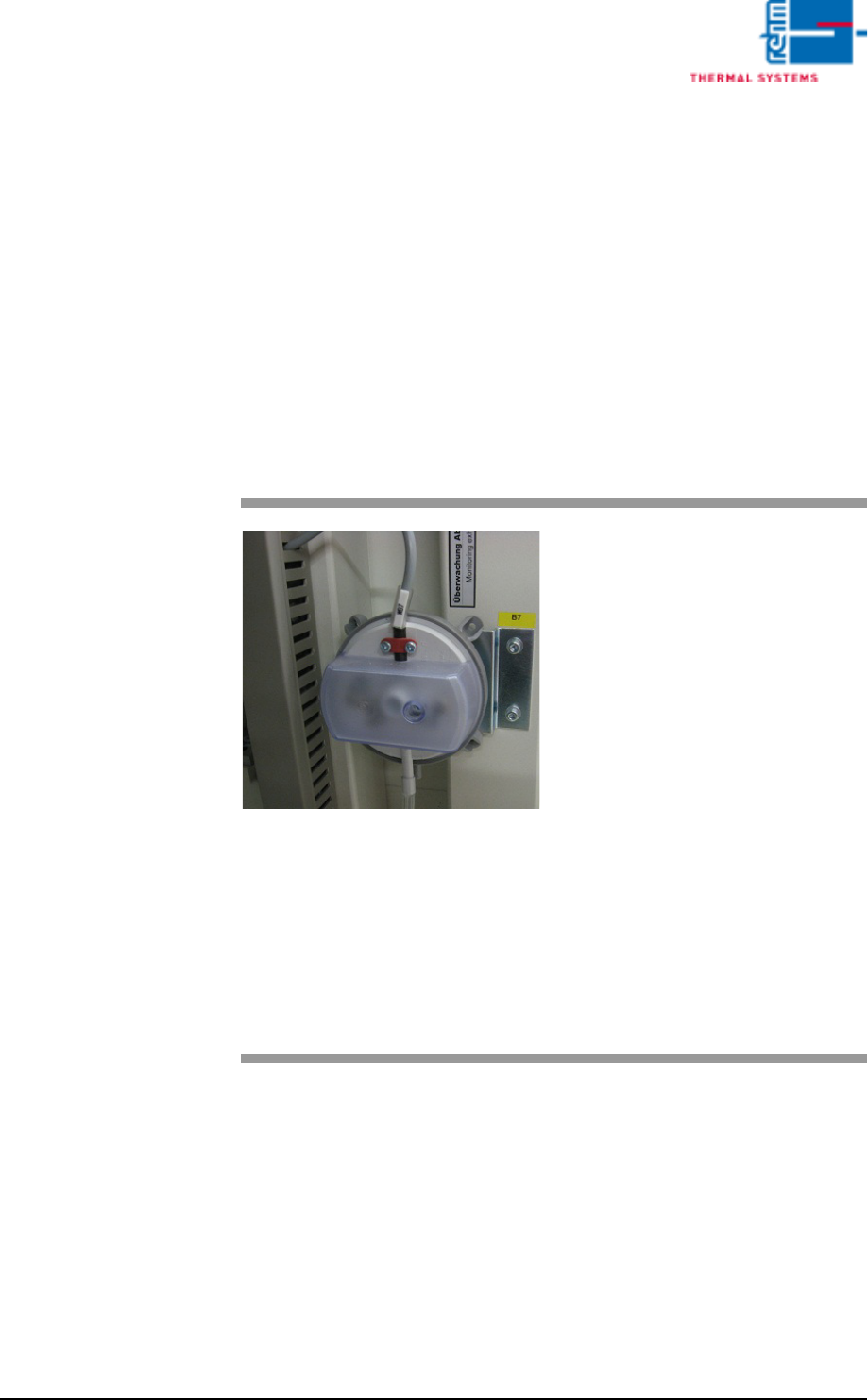
Inspection
Fig. 3-28 Exhaust Air Differential Pressure
Gauge
Procedure:
1. Unscrew the cover from the
pressure switch.
2. As long as the plant exhaust
system is switched on, the air
exhaust alarm status in the
alarm window must be green
(OK). If this is not the case, the
pressure capsule must be read-
justed.
3. Carefully pull the tube from the
capsule and check to see
whether or not the exhaust
alarm is displayed in red. If no
alarm is displayed, the pressure
capsule must be adjusted.
4. Reconnect the tube.
5. Remount the protective cover
after inspection and adjustment
have been completed.
Page 118 Vision XP+ VAC
3 Setup Instructions
3.18 Exhaust Air Monitoring
Operating Instructions
Version 1.5
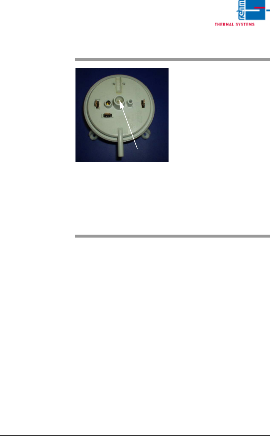
Adjustment
Fig. 3-29 Pressure Switch Adjusting Screw
1. Unscrew the cover from the
pressure switch.
2. Turn the adjusting screw anti-
clockwise to the left. The alarm
message is activated.
3. Turn the adjusting screw one
revolution in the counterclock-
wise direction. Check to see
whether or not the alarm mes-
sage is changed to green. If not,
repeat the procedure until the
alarm message is cleared.
4. Adjustment has now been
completed. The adjusting screw
should be turned only a half turn
in clockwise, in order to in-
crease the display’s tolerance
range.
5. Remount the protective cover
after inspection and adjustment
have been completed.
Adjusting Screw
Vision XP+ VAC Page 119
3 Setup Instructions
3.19 Monitoring the Water Flow Rate
Operating Instructions
Version 1.5
3.19 Monitoring the Water Flow Rate
The water connections are located at the front of the system underneath the
cooling zone.
The following conditions must be fulfilled in order to be able to monitor the
water flow rate:
• The system and the conveyor drive unit must be switched on.
• All emergency-off switches have to be unlocked in order that the water cir-
cuit has its flow again.
• The external water circuit must be connected.
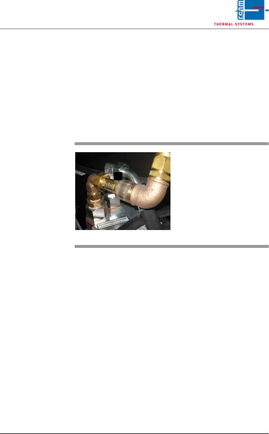
Fig. 3-30 Water Flow Rate
A)Flow rate indicator for the
external water circuit
The white marking at the
indicator must lie within the
maximum range of 8.
A