ServiceInstruction_Vision XP - 第127页
Vision XP+ V AC Page 123 3 Setup Instructions 3.22 Default V alues Operating Instructions V ersion 1.5 3.22 Default V alue s 3.22.1 Adjustment Default V alues T ab. 3-5 Adjustme nt Defaul t V alue s T ype V alue Activati…

Page 122 Vision XP+ VAC
3 Setup Instructions
3.21 Checking and Adjusting Nitrogen Pressure
Operating Instructions
Version 1.5
Prerequisites
• The system and the conveyor drive unit must be switched on.
• The heaters and nitrogen supply must be switched on.
• The plant nitrogen supply system must be connected and switched on.
• All emergency-stop buttons must be deactivated.
• It is not allowed to run a flushing phase. „The valve flushing phase“ and
„Float the insulation“ have to be switched off.
• The LED on the pressure watchdog must always be green when nitrogen
supply pressure is applied.
• If nitrogen supply fails or if there is too little pressure, the LED lights up red
and an alarm message is generated by the software.
Inspection
1. Check nitrogen pressure at the pressure gauge. (A pressure value of
5 bar is normal with activated nitrogen.)
2. Turn the regulator on the pressure gauge counterclockwise. The LED
should turn red when pressure drops below 4,5 bar. An alarm message
is generated by the software.
3. Slowly turn the regulator clockwise to 5 bar.
4. The LED is changed to green.
5. The alarm signal in the software is reset.
6. If the pressure watchdog does not indicate green even though nitrogen
pressure is correct, or if green is indicated even though there is no
pressure, the watchdog must be adjusted.
Adjustment
1. Remove the cap from the pressure watchdog with the help of a screw-
driver (see also Fig. 3-30, on page 108).
2. Loosen the lock nut with an open-end wrench.
3. When nitrogen pressure has reached a value of 5 bar, turn the adjusting
screw clockwise with a hex key until the LED lights up red.
4. Slowly turn the adjusting screw counterclockwise until the LED turns
from red to green.
5. Turn the adjusting screw an additional half revolution in order to in-
crease the tolerance range.
6. Tighten the lock nut and replace the cap.
Vision XP+ VAC Page 123
3 Setup Instructions
3.22 Default Values
Operating Instructions
Version 1.5
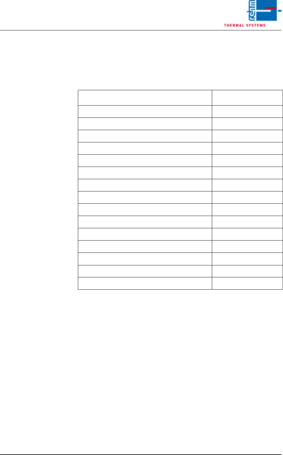
3.22 Default Values
3.22.1 Adjustment Default Values
Tab. 3-5 Adjustment Default Values
Type
Value
Activation Temperature Pyrolysis 210°C
Switch off temperature 90°C
Conveyor adjustment 90°C
Pause duration 5 s
Conveyor adjustment, Number of cycles 1
Referencing every 3 Days
Relay Typ SS/CR
Autostart On
Activate Fifo Off
Activate Pin - In - Paste Off
Increase PCB width after program change Off
Filter F9 Check while Referencing Off
Signaling Manual Loading Off
Cycle medium injection 00:30 mm:ss
Impulse medium injection 20 x 0,1 s

Page 124 Vision XP+ VAC
3 Setup Instructions
3.22 Default Values
Operating Instructions
Version 1.5
3.22.2 Alarm Configuration Default Values
Alarm
Response
Type
Warning
Time Alarm Time
Emergency-Stop 17 0 0
Phase Monitoring 16 0 0
Motor Protection 16 0 0
Frequency Converter 16 20 10
Frequency Cooling Tract 5 20 10
Cooling section 5 0 0
Fan Monitoring 16 20 10
Exhaust 4 10 0
Process Chamber Open 5 0 0
Heating Elements Monitoring 4 10 0
Excess temperature protection
was released
16 0 0
Drive Motor 1 0 0
Condensate Trap 3 0 0
Condensate trap error 3 0 0
Power supply error 16 0 0
Cooling tract circulation 4 10 0
Standstill Monitoring 17 10 30
Speed Tolerance Violation 3 10 0
Upper Temperature Limit Value 16 5 10
Maximum Temperature Toler-
ance
3 0 120
Minimum Temperature Toler-
ance
3 0 120
Heating element power control-
ler error
4 10 0
PCB Feed Monitoring, Lane 1 3 10 0
PCB Transfer jam, Lane 1 16 0 30
Outlet Interface, Lane 1 (with
Siemens-Interface only)
1 0 0
Error Circuit, Lane 1 1 0 0