ServiceInstruction_Vision XP - 第130页
Page 126 Vision XP+ V AC 3 Setup Instructions 3.22 Default V alues Operating Instructions V ersion 1.5 3.22.3 Frequency Converter Parameter Default V al ues VXP+ T ab . 3-7 Frequen cy Con verter Para meter (de fault val …
Vision XP+ VAC Page 125
3 Setup Instructions
3.22 Default Values
Operating Instructions
Version 1.5
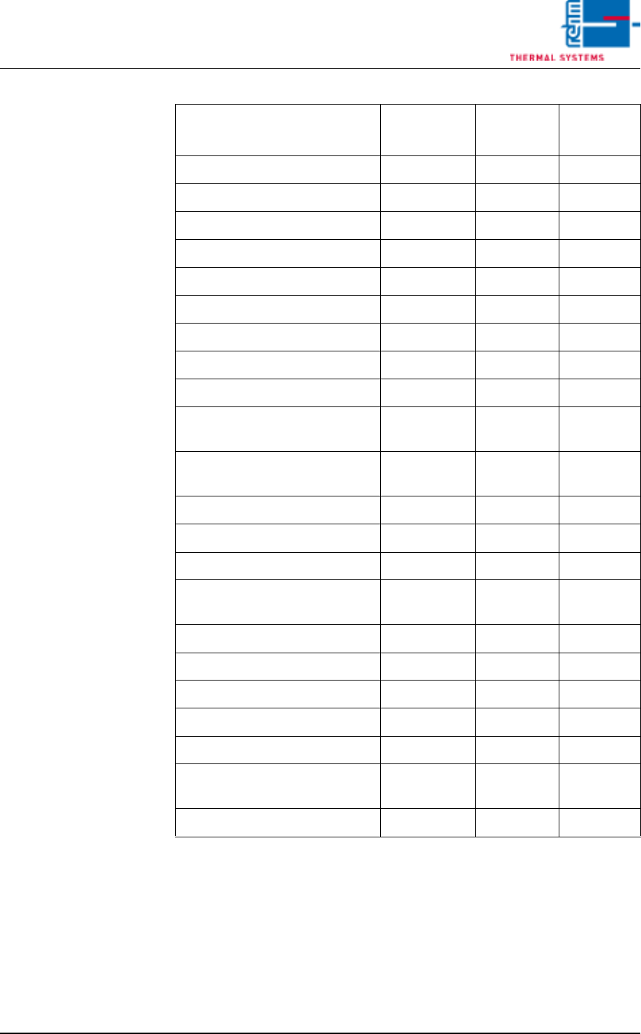
Tab. 3-6 Alarm Configuration (default values)
Cooling water 16 10 10
Too little water 24 10 720
Water Leak 16 0 0
Cooling System 3 10 0
N2 consumption OK 1 20 0
N2/O2 Pressure to low 4 30 0
Residual Oxygen Meter 4 10 0
O2 Tolerance Violation 3 5 0
Condensation bottles are full 24 10 720
Flow monitoring residue man-
agement
4 180 180
Filling level Chain Lubricator too
low.
24 10 720
SPS Field Modules 16 0 0
SPS Communication 1 2 0
Transport adjustment OK 3 0 0
Supervision of PCB-dropping
was released
16 1 0
Conveyor Adjustment Current 14 0 0
Conveyor Drive Current 3 10 0
MES Release 0 0 0
PCB Feed Monitoring, Lane 2 3 10 0
PCB Transfer, Lane 2 16 0 30
Outlet Interface, Lane 2 (with
Siemens-Interface only)
1 0 0
Error Circuit, Lane 2 1 0 0
Alarm
Response
Type
Warning
Time Alarm Time
Page 126 Vision XP+ VAC
3 Setup Instructions
3.22 Default Values
Operating Instructions
Version 1.5
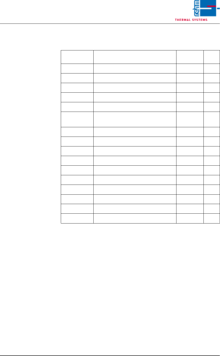
3.22.3 Frequency Converter Parameter Default Values VXP+
Tab. 3-7 Frequency Converter Parameter (default values)
They are mounted optionally as 7 frequency converters, the numbers of fre-
quency converters have to be allocated to the appropriate system areas.
The settings of the frequencies of each area remain default values.
Frequency
Converter No.
Function Frequency Activ
1 Preheating on top (zone 1-8) 40 Hz Yes
2 Preheating down (zone 1-8) 45 Hz Yes
3 Peak on top (Peak zone 1-3) 40 Hz Yes
4 Peak down (Peak zone 1-3) 45 Hz Yes
5 Cooling Zone 1 35 Hz Yes
6 Cooling Zone on top (Cooling Zone 2-
4)
40 Hz Yes
7 Vacuumchamber 20-25 Hz Yes
8 Option No
9 Option No
10 Option No
11 Option No
12 Option No
13 Option No
14 Option No
15 Option No
16 Option No
Vision XP+ VAC Page 127
3 Setup Instructions
3.22 Default Values
Operating Instructions
Version 1.5
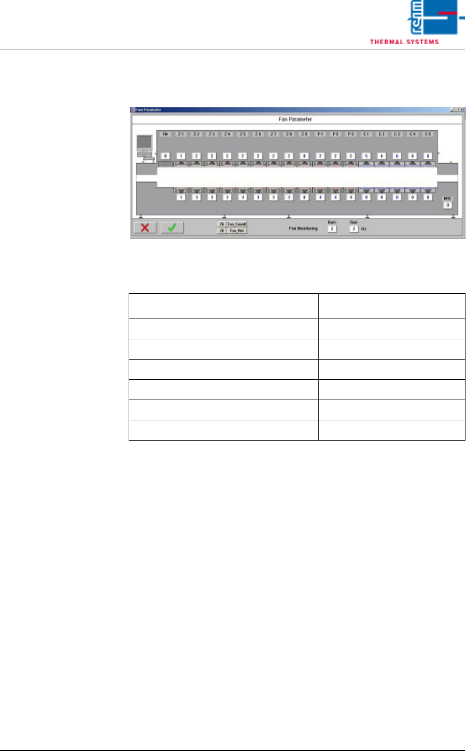
3.22.4 Fans Monitoring Default Values
Fig. 3-33 Fans Parameter (example)
Tab. 3-8 Fans Monitoring (default values)
They are mounted optionally as 7 frequency converters, the numbers of fre-
quency converters have to be allocated to the appropriate system areas.
Fans Position
Entry Frequency Converter No.
Preheating on top (zone 1-8) 1
Preheating down (zone 1-8) 2
Peak on top (Peak zone 1-3) 3
Peak down (Peak zone 1-3) 4
Cooling Zone 1 5
Cooling Zone on top (Cooling Zone 2-4) 6