ServiceInstruction_Vision XP - 第19页
Vision XP+ V AC Page 15 2 Maintenance 2.5 Process chamber Operating Instructions V ersion 1.5 2.5 Proces s chambe r 2.5.1 Cleaning the Interior Fig. 2-3 Clea ning the I nterior Consumable materi als: • Oven cleaner • Rag…

Page 14 Vision XP+ VAC
2 Maintenance
2.4 Inlet
Operating Instructions
Version 1.5
2.4 Inlet
2.4.1 Optical fibre sensor at the inlet area
Fig. 2-1 Optical fibre sensor at the inlet
Fig. 2-2 Optical fibre sensor at the inlet
The plant has an optical fibre sensor
at its inlet. This optical fibre sensor
is used for PC board identification.
The specified set-point value of this
sensor is between
100 - 250 digits.
Rehm Thermal Systems techni-
cians preset the switching threshold
to 350 digits for a single track and
500 digits for a dual track.
The PC board will be detected when
the threshold level is exceeded.
The degree of soiling is determined
as a percentage. An alarm will in ad-
dition be triggered in the display
should this approach the threshold
level.
To continue proper operation, the
sensor should then be cleaned as
soon as possible, using an appropri-
ate cleaning agent.
The settings are based on Rehm
Thermal Systems experience.

Vision XP+ VAC Page 15
2 Maintenance
2.5 Process chamber
Operating Instructions
Version 1.5
2.5 Process chamber
2.5.1 Cleaning the Interior
Fig. 2-3 Cleaning the Interior
Consumable materials:
• Oven cleaner
• Rags
Procedure:
1. Raise the process chamber as
far as it will go.
2. Clean the process chamber
floor and side panels with oven
cleaner and a rag.
3. Clean the heater nozzles and
the nozzle sheets in the peak
zone.
4. Remove stubborn incrustations
with the putty knife.
Page 16 Vision XP+ VAC
2 Maintenance
2.5 Process chamber
Operating Instructions
Version 1.5
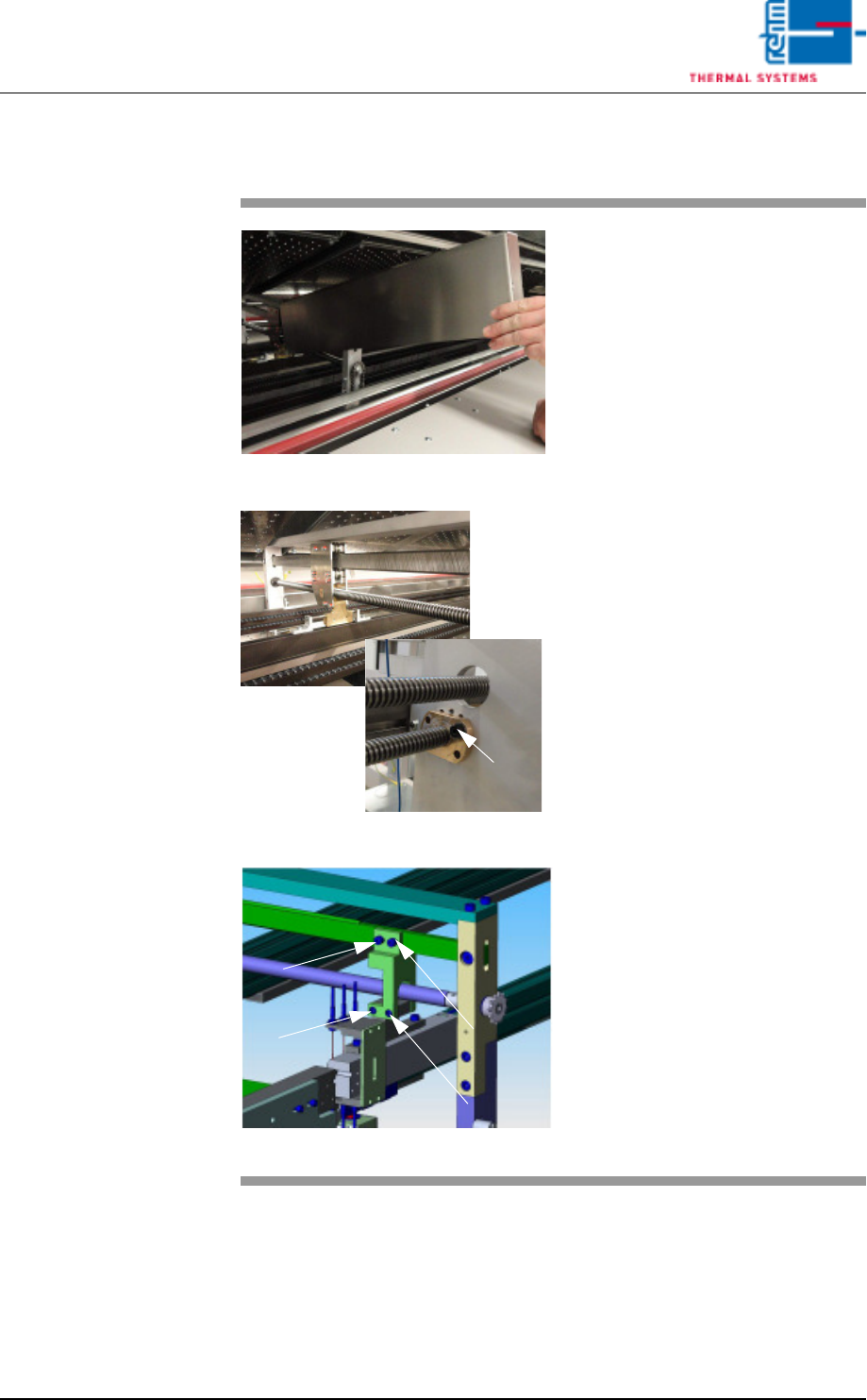
2.5.2 Cleaning of oven stations
Fig. 2-4 cleaning of oven station
Fig. 2-5 cleaning of oven station
Fig. 2-6 Oven station CAD
Expendable materials:
• Oven cleaning agent
• Cleaning cloths
• Paint brush
• Chain oil Addinol
Procedure:
1. Remove the cover of the oven
station.
2. Clean spindles from the PCB and
CBS width adjustment at the inlet
and the outlet as well as the oven
stations with cleaning cloths and
oven cleaning agent.
3. Oil the spindles with the paint
brush after the cleaning.
4. Check the spindle nut regularly
for „clearance“.
5. This oven station picture (CAD)
shows the screws to regularly
check and retighten as neces-
sary.
Spindle nut