ServiceInstruction_Vision XP - 第32页
Page 28 Vision XP+ V AC 2 M aintenance 2.7 Co oling T ra ct Operating Instructions V ersion 1.5 2.7.2 Additional cleaning chute VXP+ Fig. 2-3 4 Additio nal clea ning chu te Fig. 2-3 5 Additio nal cleanin g chute 1 Consum…
Vision XP+ VAC Page 27
2 Maintenance
2.7 Cooling Tract
Operating Instructions
Version 1.5
2.7 Cooling Tract
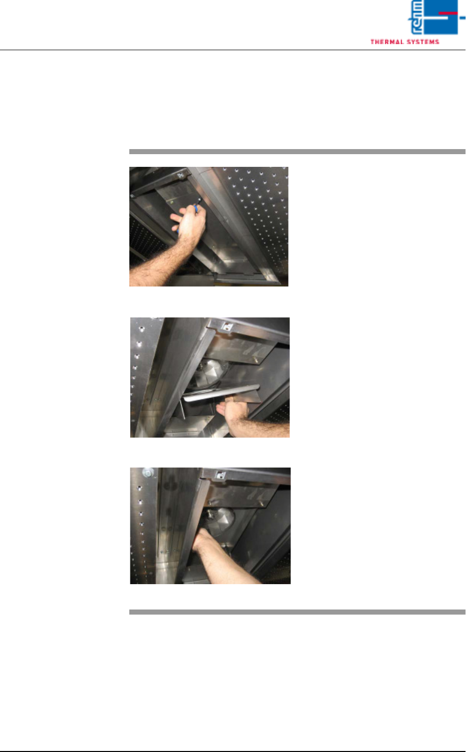
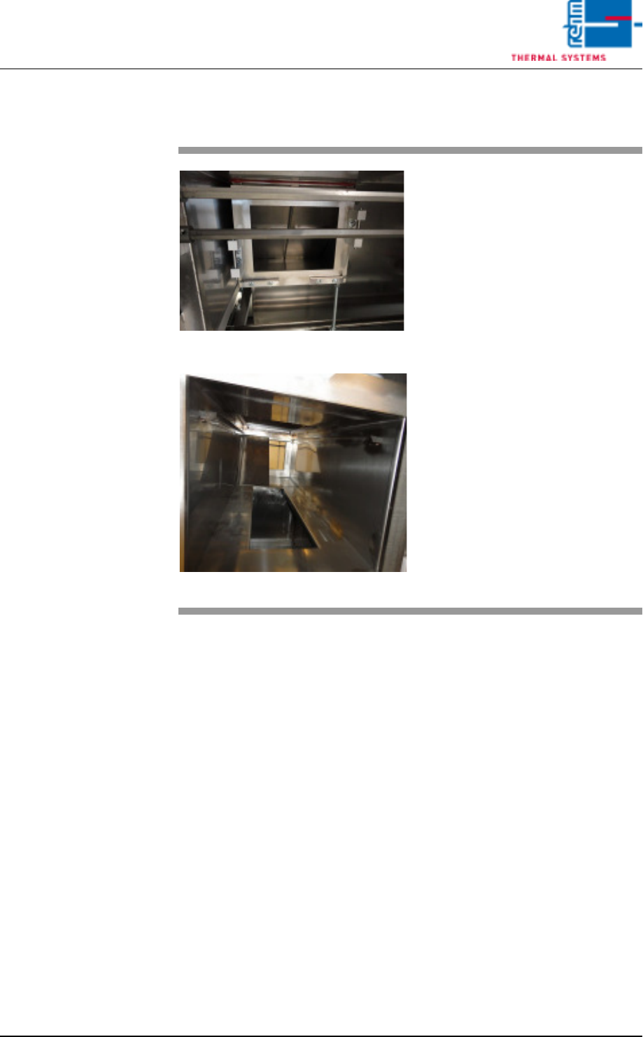
2.7.1 Cleaning the Cooling zone (passive area)
Fig. 2-31 Cover for Suction Chamber
Fig. 2-32 Sheet Metal Cover on Impeller
Fig. 2-33 Fan Impeller
The cooling zone can be dismantled
as described below. The individual
parts (e.g. nozzle field etc.) are
cleaned in a rinsing bath, or with
oven cleaner and rags.
Consumable materials, tools:
• Oven cleaner CF 1
• Rags
• Or rinsing bath
Procedure:
1. Loosen the screws on the noz-
zle sheet and lift it out.
2. Unscrew suction chamber cov-
er (see Fig. 2-31).
3. Remove the sheet metal cover
from the impeller (see Fig. 2-
32).
4. The fan impeller is now ex-
posed and can be inspected,
and cleaned with oven cleaner
and rags (see Fig. 2-33).
Page 28 Vision XP+ VAC
2 Maintenance
2.7 Cooling Tract
Operating Instructions
Version 1.5
2.7.2 Additional cleaning chute VXP+
Fig. 2-34 Additional cleaning chute
Fig. 2-35 Additional cleaning chute 1
Consumables:
• Oven cleaner
• Cleaning rags
• Cleaning bath
An additional cleaning chute for the
cooling section is fitted at the front of
the plant.
This chute simplifies cleaning of the
cooling chute; the partitioning plates
may be individually removed and
placed in a suitable cleaning bath.
The cooling chute may now be
cleaned on both sides.
Thereafter reassemble everything
in reverse order.
Vision XP+ VAC Page 29
2 Maintenance
2.7 Cooling Tract
Operating Instructions
Version 1.5
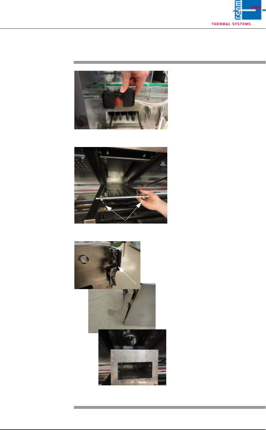
2.7.3 Clean cooling module 1 VXP+
Fig. 2-36 Disconnect power supply
Fig. 2-37 Lower nozzle field
Fig. 2-38 Unlatch, remove the cooling mod-
ule
Consumables, tools:
• Oven cleaner
• Cleaning rags
• Cleaning bath
Procedure:
1. First disconnect the electric
heater supply at the back of
the plant. Then pull out the
heater at the back.
Now remove cooling module 1
at the front of the machine for
cleaning, as follows.
2. Rotate the wing screws at the
right and left at the nozzle field
by 90°, remove the metal safety
plate with a knurled screw and
lower the nozzle field for
cleaning.
3. Release the cooling cartridge’s
tension lock, raise the cartridge
and lift it forwards and out.
4. Place the cooler cassette in the
cleaning bath.
5. Also clean the inside area as
well as the fan wheel.
6. Re-fit the cleaned cooler
cassette.
7. Push the heater at the back of
the machine back in and plug in
the power supply.