ServiceInstruction_Vision XP - 第61页
Vision XP+ V AC Page 57 2 Maintenance 2.15 Conveyor System Operating Instructions V ersion 1.5 2.15 Conveyo r System 2.15.1 Chain Lubricator – Checking and Refilling the T ank Fig. 2-9 8 Cha in lubric ating pumps with tw…
Page 56 Vision XP+ VAC
2 Maintenance
2.14 Residual Oxygen Meter
Operating Instructions
Version 1.5
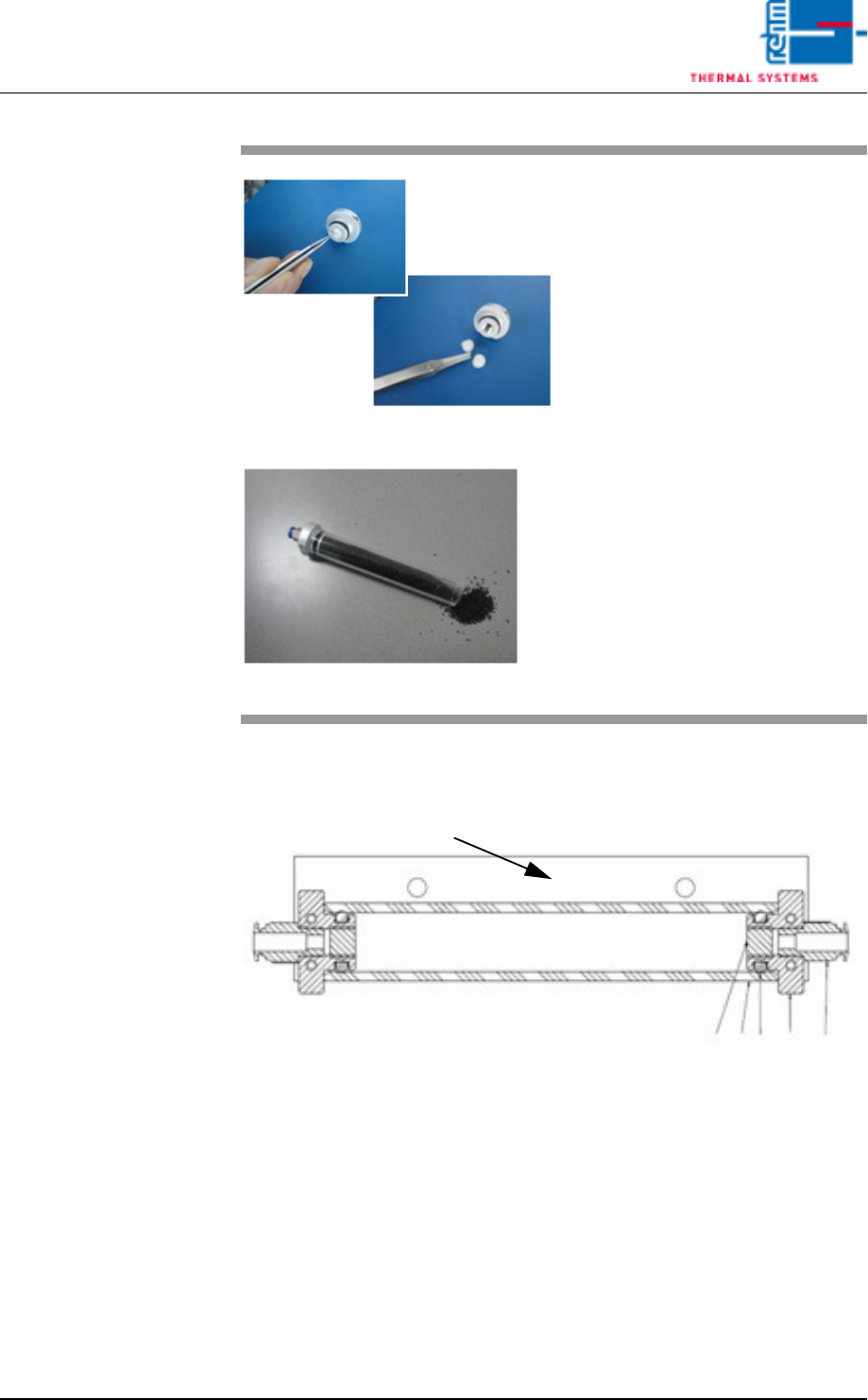
Detail drawing of the activated carbon filter on the adapter plate.
1. Cover activated carbon filter
2. Tube activated carbon filter
3. Woven filter medium
4. Plug-in connection QS – 1/8-6
5. O-Ring 12 x 4 mm
6. Adapter activated carbon filter
Fig. 2-96 Exchange activated carbon
Fig. 2-97 Exchange activated carbon
Now, exchange each one non-wo-
ven insertions on both sides of the
activated carbon filter with the twee-
zers.
Exchange activated carbon and
densify it.
Now, mount everything in reversed
order.
6
3
2
5
1
4
Vision XP+ VAC Page 57
2 Maintenance
2.15 Conveyor System
Operating Instructions
Version 1.5
2.15 Conveyor System
2.15.1 Chain Lubricator – Checking and Refilling the Tank
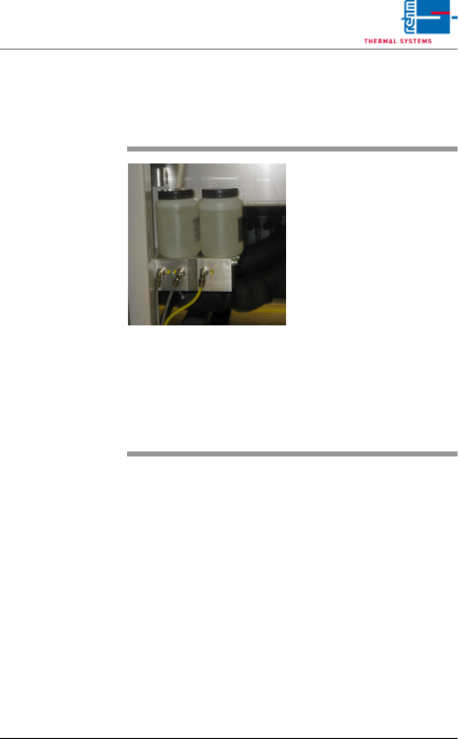
Fig. 2-98 Chain lubricating pumps with two
and one outlet
The chain lubricator is located on
the operator side behind the second
door on the right.
There are two chain lubricating
pumps in the VXP system, each
with one or two outlets.
Consumable materials, tools:
• Chain fluid
Procedure:
1. Fill to a level of about 1 cm be-
low the brim.
2. Inspect to make sure that the
hose connectors are securely
attached to the lubricator units.
Caution!
The chain lubricator should not be
allowed to run completely empty,
because if the pump runs dry dam-
age may result.
Page 58 Vision XP+ VAC
2 Maintenance
2.15 Conveyor System
Operating Instructions
Version 1.5
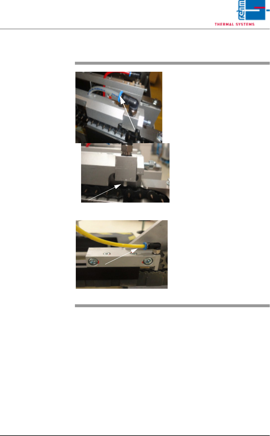
2.15.2 Chain oiler maintenance VXP+
Fig. 2-99 Transport chain oiler (top)
Fig. 2-100Chain oiler - MU (bottom)
Consumable materials, tools:
• Chain Fluid
Procedure:
1. Apply the chain oil to the trans-
port chains by droplets.
2. Check the chain oiler settings in
the controller if there is no chain
oil. Start the chain oiler manual-
ly and check if oil reaches the
oiling unit.
3. Also ensure that the outlet is not
blocked.
4. Pull the Festo hose from the an-
gle unit and blow through with
compressed air. Then plug
back the hose properly.