ServiceInstruction_Vision XP - 第79页
Vision XP+ V AC Page 75 3 Setup Instructions 3.3 Conveyor Operating Instructions V ersion 1.5 3.3 Conveyo r 3.3.1 Conveyor Drives Fig. 3-6 Conve yor Dri ve Param eters A) Lane T ype 0 = no lane 1 = lane B) Speed T ype 0 …
Page 74 Vision XP+ VAC
3 Setup Instructions
3.2 Temperature Channels
Operating Instructions
Version 1.5
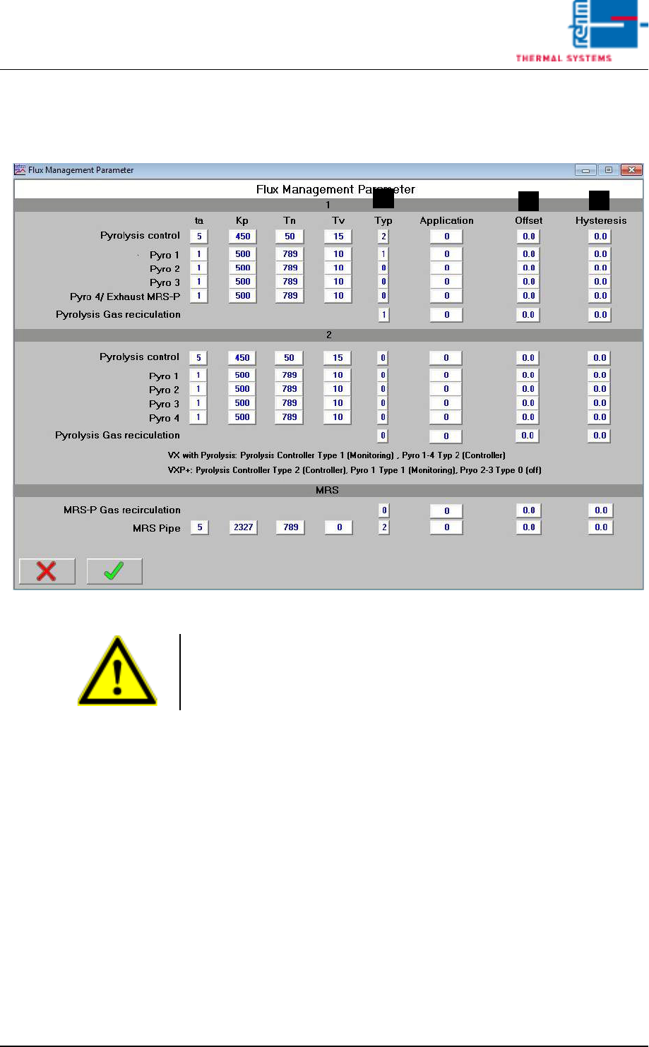
3.2.3 Flux Management Parameter
Fig. 3-5 Flux Management Parameters
A) Typ
VX with pyrolysis: Pyrolysis control Type 1 (monitor)
Pyrolysis 1 - 4 Type 2 (controller)
VXP+: Pyrolysis control Type 2 (controller)
Pyrolysis 1 Type 1 (monitor)
Pyrolysis 2 – 3 Type 0 (off)
B) Offset
Deviation at the temperature display can be compensated for with the
offset function.
C) Hysteresis
Tolerance evaluation performance can be adapted with the hysteresis
function.
B
A
C
Caution!
Values are system-specific and may only be changed by service personnel
from Rehm Thermal Systems GmbH!
This value may only be changed when heat is turned off.
Vision XP+ VAC Page 75
3 Setup Instructions
3.3 Conveyor
Operating Instructions
Version 1.5
3.3 Conveyor
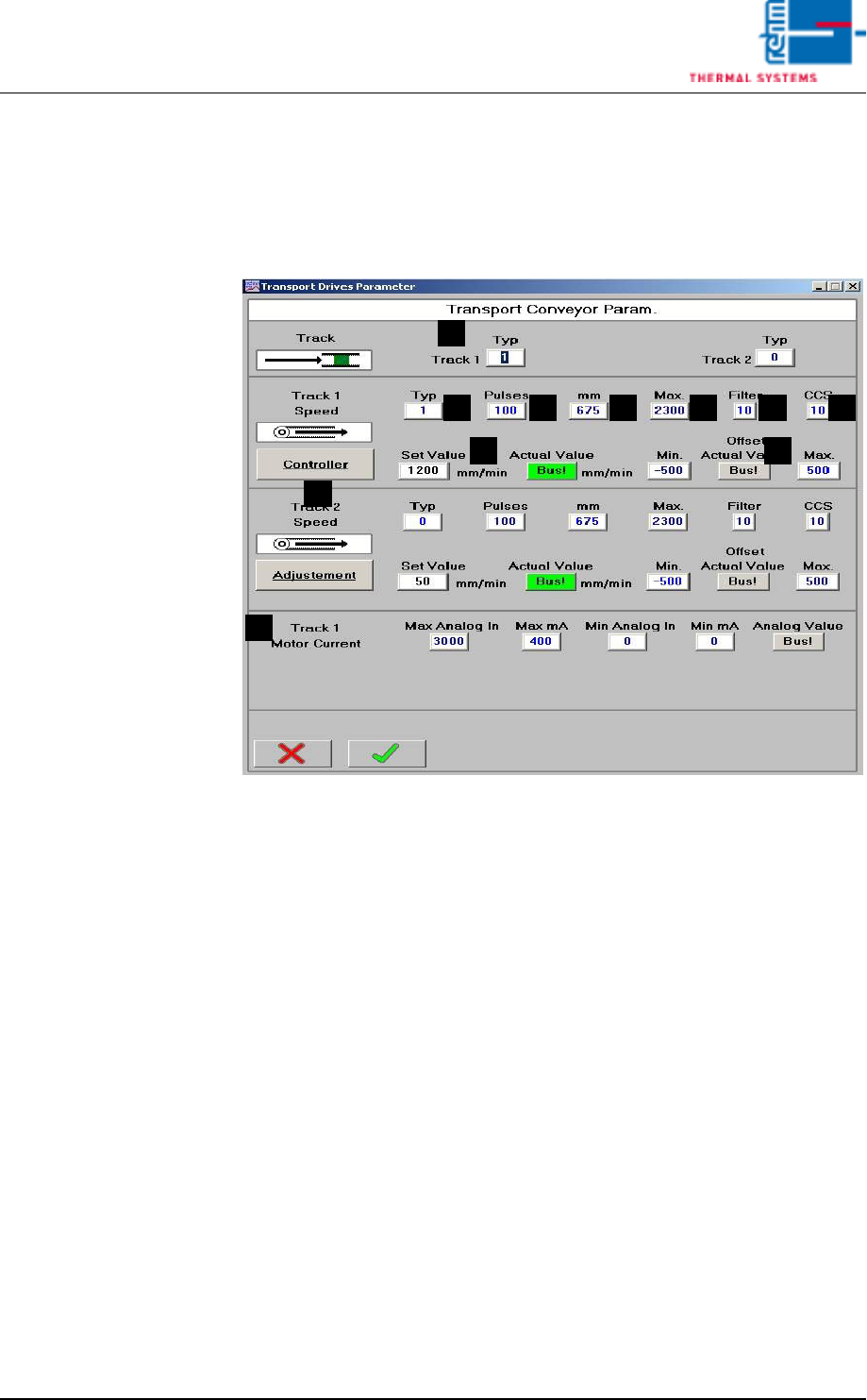
3.3.1 Conveyor Drives
Fig. 3-6 Conveyor Drive Parameters
A) Lane Type
0 = no lane
1 = lane
B) Speed Type
0 = lane does not have its own drive motor
1 = lane has its own drive motor
C) Pulses
Number of belt pulses which corresponds to the entered travel path (D).
The default setting is 100 mm.
D) Travel distance in mm, which corresponds to the entered number of belt
pulses (C). The default setting is 675.
With this value the difference between the actual speed and the indicated
actual value can be adjusted. Please note! A change is only permitted,
if anything has changed at the transformation ratio.
E) Max
Maximum possible speed based on electromechanical limitations. The
actual maximum possible speed is limited by the software. The default
setting is 2300.
With this value a difference between actual speed and entered set value
can be adjusted. Please note! A change is only permitted, if anything has
changed at the transformation ratio.
A
FEDCB
I
H
G
J
K

Page 76 Vision XP+ VAC
3 Setup Instructions
3.3 Conveyor
Operating Instructions
Version 1.5
F) Filter
Number of measured values which are averaged together for the actual
value display. A high number results in a stable display value, although
changes to the display value appear very slowly in this case. The default
setting is 10.
G) CCS
Number of measured values which are averaged together for CCS data
logging. This value must correspond with the CCS software settings. The
default setting is 10.
H) Offset
In the closed-loop control mode, the difference between the setpoint and
the actual value is continuously ascertained. An offset is generated
cyclically from this difference for the motor controller module. The current
offset value is displayed here, and minimum and maximum values can be
entered. The default setting is ± 500.
I) Setup Mode / Closed-Loop Control Mode
Settings can be adjusted at the motor controller module in the setup
mode. Offset for the motor controller module is deactivated.
Settings may not be adjusted at the motor controller module in the
closed-loop control mode. Offset for the motor controller module is
activated.
The default setting is closed-loop control mode.
J) Setpoint / Actual Value
Conveyor speed is changed by entering a new setpoint (white field). The
actual value is displayed in the adjacent field.
K) Motor current
Set speed to1800 mm per minute. Switch the conveyor on a read the an-
alog value. Enter this value to „Max. Analog IN“. Connect the ammeter in
series to the motor and read the actual value (mA). Enter the mA value
to „Max. mA“.
To make check the
Speed
1. Turn the conveyor on and check to see whether or not the belt pulse
sensor switches accurately.
2. Open the conveyor window.
3. Set the speed setpoint to 1000 mm per minute, and set manipulated
variable limiting Ymax to 100%.
4. Open the Conveyor Drives window from the service menu.
5. Make sure that switch I is set to setup mode. If not, click switch I. The
text is changed from “Closed-Loop Control Mode” to “Setup Mode”.
6. In order to determine conveyor speed, time required for 1000 mm of
travel must be checked with the help of a stopwatch and a link pin
identified for this purpose.
7. Set switch I back to closed-loop control mode.
8. Save the system parameters to memory.