ServiceInstruction_Vision XP - 第88页
Page 84 Vision XP+ V AC 3 Setup Instructions 3.5 Frequency Converter Operating Instructions V ersion 1.5 3.5 Frequency Convert er Fig. 3-1 0 Frequen cy Con verter Para meters Frequency co nverter parameters a re entered …
Vision XP+ VAC Page 83
3 Setup Instructions
3.4 Alarm Configuration
Operating Instructions
Version 1.5
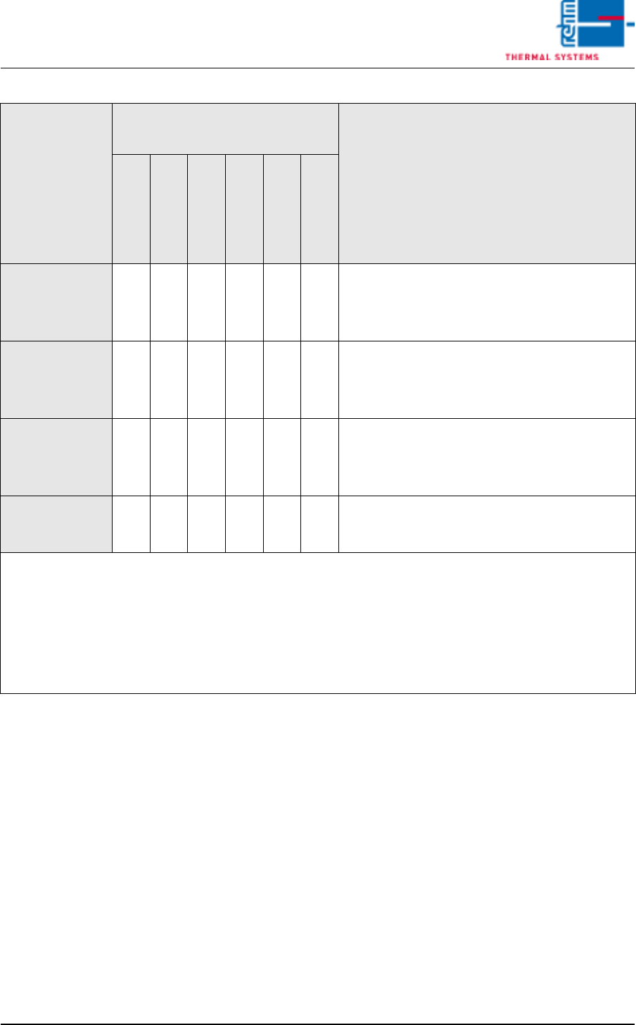
Tab. 3-1 Alarm Types
24
-- -- t1 t1 t1 t1 Type 23 + red after t1
Can be acknowledged manually after t1 has
elapsed, and the error must be eliminated after
t2 has elapsed.
26
t2 -- t1 t1 t1 t1 Type 24 + heat off after t2
Can be acknowledged manually after t1 has
elapsed, and the error must be eliminated after
t2 has elapsed.
27
t2 t2 t1 t1 t1 t1 Type 26 + heat and conveyor off after t2
Can be acknowledged manually after t1 has
elapsed, and the error must be eliminated after
t2 has elapsed.
33 -- -- -- t1 t1 t1 Type 3
Can be acknowledged manually after t1 has elapsed
no action after t2
Seconds are entered for t1 and t2. Minutes are only entered for t2 in the case of alarm types 23,
24, 26 and 27.
If the horn is acknowledged during t2, it sounds once again after t2 has elapsed. With an alarm type 33 never
enter Zero in t2.
Two-digit response types must be acknowledged in any event after t2 has elapsed and the error
has been eliminated, even if the horn has been previously acknowledged.
If response types other than those shown above are entered, the same response is triggered as
for response type 17!
Response After Warning Time (t1) or
Response Time (t2)
Response Type
Heat
Drive Unit
Red lamp
Horn
Yellow lamp
Display
Comment
Page 84 Vision XP+ VAC
3 Setup Instructions
3.5 Frequency Converter
Operating Instructions
Version 1.5
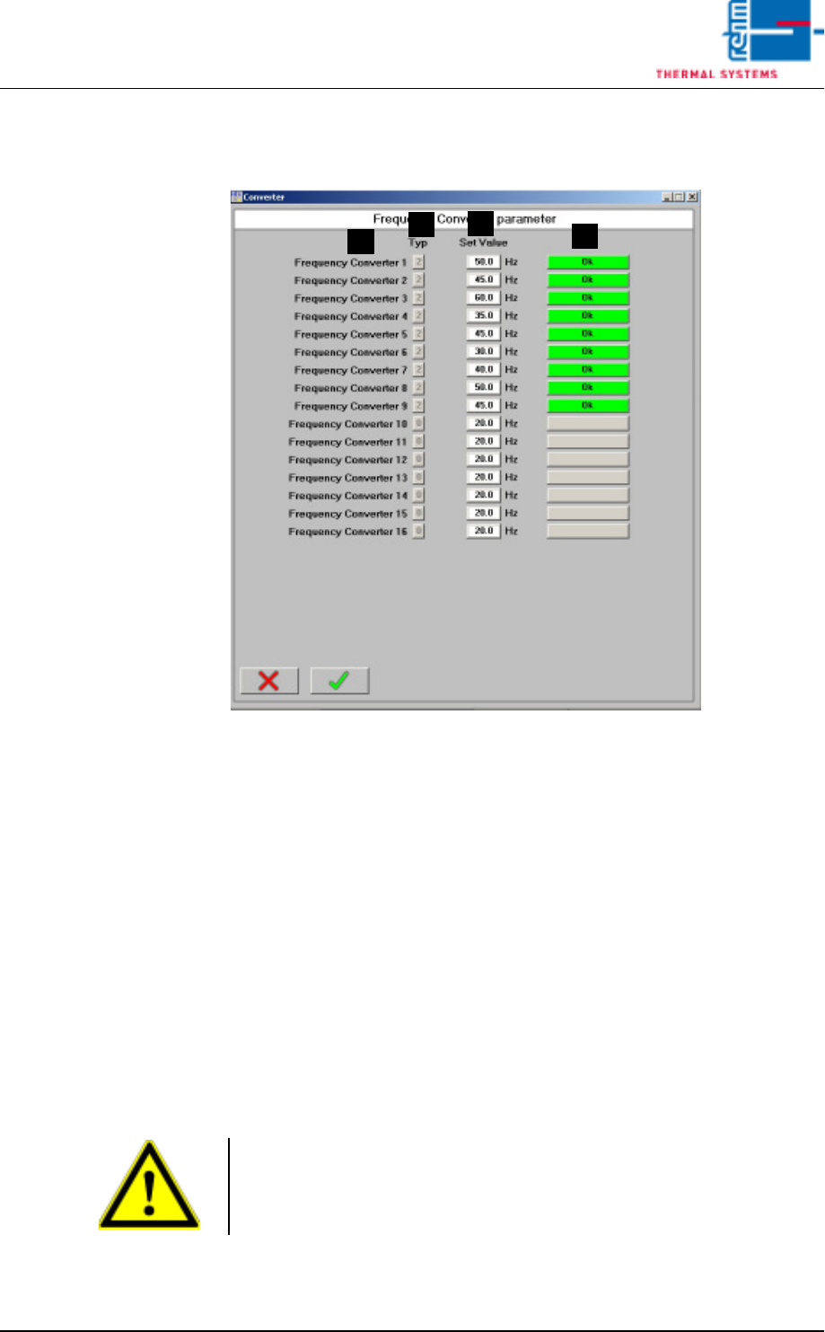
3.5 Frequency Converter
Fig. 3-10 Frequency Converter Parameters
Frequency converter parameters are entered to this window.
A) Designation of the frequency converter
B) Type
Only relevant if a B&R controller is used in combination with a Mitsubishi
frequency converter
0 = no frequency converter
1 = frequency converter, inactive
2 = frequency converter, active
3 = parameters configuration
C) Setpoint
Frequency setpoint for the respective converter
D) Status
Only relevant if a B&R controller is used in combination with a Mitsubishi
frequency converter
A
C
B
D
Note!
Frequency converters 13 to 16 are operated with their own set values in
standby mode and not with the values given by the standby mode. This is
necessary for example on machines with MRS-P.

Vision XP+ VAC Page 85
3 Setup Instructions
3.5 Frequency Converter
Operating Instructions
Version 1.5
3.5.1 Typ Mitsubishi FR-D 700
Setting system
parameters
In connection with a B & R control
1. Start with point 2 if the frequency converters are not activated.
As long as the system conveyor is running, a signal is applied to all of
the frequency converters, and input to the frequency converters is
blocked. The frequency converter is disabled with the STOP key.
2. Press the Mode key. A random parameter appears at the display. Select
parameter P 79 with the Digital Dial (knop).
Press the Set key and set the value to 1 with the Digital Dial. Press the
Set key to acknowledge the setting.
3. The parameter to be changed can now be selected by turning the Digital
Dial. The following, for example, appears at the display:
“P 7. ATTENTION!”. If parameter 30 has a value of 0, only parameters
0 through 9, 30 and 79 can be displayed. If all parameters are to be
selected, parameter 30 must be set to 1.
4. The current value for the selected parameter is displayed by pressing
the Set key.
5. The new value can now be selected with the Digital Dial.
6. The newly selected value is then saved to memory by activating the Set
key. The display returns once again to the parameters window.
7. Steps 3 through 6 must then be repeated if additional parameters need
to be changed.
Attention!
The heaters may not exceed a temperature of 70° C, because the fans
might otherwise overheat.
Note!
The frequency converters can only be parameterized when the heating fan
and the conveyor system stopped.