ServiceInstruction_Vision XP - 第96页
Page 92 Vision XP+ V AC 3 Setup Instructions 3.5 Frequency Converter Operating Instructions V ersion 1.5 Note! Special se ttings should only be en tered by the service department from Rehm Therma l Systems.
Vision XP+ VAC Page 91
3 Setup Instructions
3.5 Frequency Converter
Operating Instructions
Version 1.5
3.5.3 Siemens Type MM 420 with Profibus - Connections
Setting system
parameters
1. If the frequency converter is already running, the controller must first be
disabled with the 0 key (STOP).
2. Press the “P” key in order to change the parameter settings (P000
appears at the display).
3. Select the desired parameter with the ñ or the ò key.
4. The current parameter value can be displayed by pressing the “P” key.
5. Change the parameter value with the ñ or the ò key, and save to mem-
ory with the “P” key.
6. Press the ò key until P000 appears at the display in order to exit the pa-
rameter setting function. Then press the “P” key. Output frequency and
the frequency setpoint are now displayed alternately.
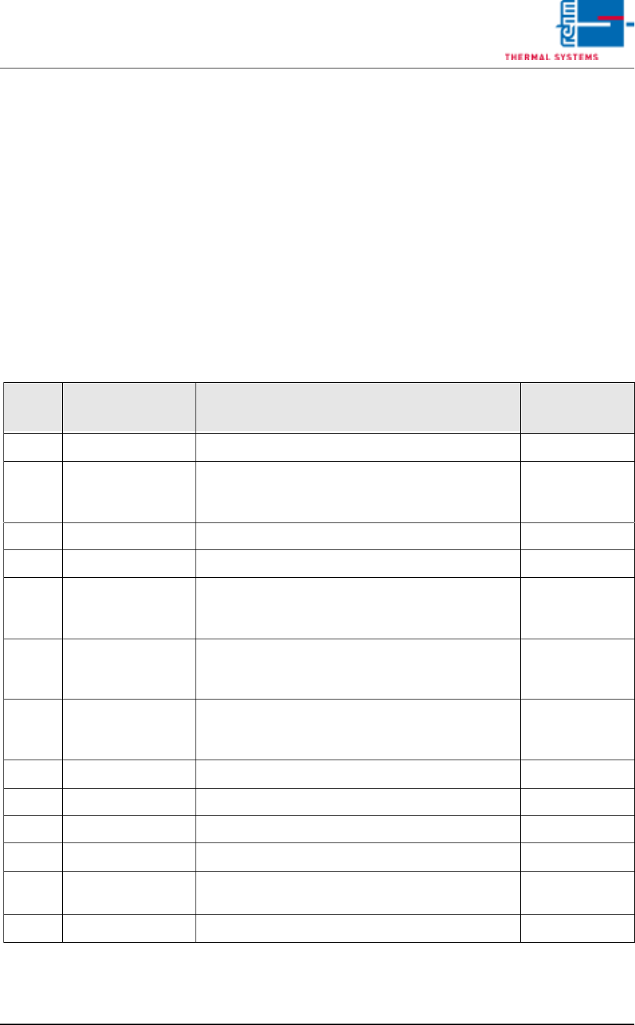
Tab. 3-4 Siemens Type Micromaster MM420 – Parameters
Para-
meter Function Description of Selected Parameters
Setting Values
for this System
P003 Access authority All parameters can be read and adjusted. 3
P0304 Nominal motor
voltage (serial
plate)
400 (V)
P0701 Digital input 1 Fixed frequency (on + reverse) 2
P0731 Digital output 1 High = converter running 52.2
P1000 Frequency setpoint
(communications
modul)
Selects the source of the frequency setpoint. 6
P1080 Minimum frequen-
cy
Sets motor frequency to the smallest value (Hz)
with which the motor functions independent of the
frequency setpoint.
20 (Hz)
P1082 Maximum frequen-
cy
Sets motor frequency to the highest value (Hz) with
which the motor functions independent of the fre-
quency setpoint.
60 (Hz)
P1121 Resetting time Delay time from the highest frequency to standstill 20 (s)
P1210 Automatic Restart Automatic Restart after Line Voltage Dip or Error 3
P1300 Control concept Quadratic voltage-frequency curve 2
P1800 Pulse frequency Pulse frequency of the frequency converter 2
P2000 Reference fre-
quency
Reference frequency of the analog input 100 (Hz)
P971 RAM in ROM load Parameter power cut - proof 1

Page 92 Vision XP+ VAC
3 Setup Instructions
3.5 Frequency Converter
Operating Instructions
Version 1.5
Note!
Special settings should only be entered by the service department from
Rehm Thermal Systems.

Vision XP+ VAC Page 93
3 Setup Instructions
3.6 Fan Parameters
Operating Instructions
Version 1.5
3.6 Fan Parameters
Fig. 3-11 Fan Parameters
The fan monitoring parameters are entered to this window.
A) Converter Assignment
Which fan will be controlled by which converter can be selected here.
0 = no fan, or fan monitoring not activated for this fan
1.16 = number of the desired frequency converter
20.60 = entry of a fixed frequency setpoint for this fan
B) Fan_Count
The number of defective fans is displayed here.
C) Fan_No.
The index number of the defective fan is displayed. In the event of more
than one defect, the highest index number is displayed.
D) Fan supervision
Input for tolerance of the fan supervision. Standard value is 2 Hz. When
exceeding the allocated frequency by 2 Hz an alarm fan supervision fail-
ure is triggered off.
C
B
A
A
D