Head PCB - Overview en - 第10页
Description of the Circuit Boards CP12:CP6 SP_12 Digital Intermediate Distributor [00330648-05] 10 Head PCB Overview Ste p by Step An alysis Connectors Description X1, 40-pin Connected to plug X14 on the head boar d ▪ Vo…
Description of the Circuit Boards CP12:CP6
SP_12 Digital Intermediate Distributor [00330648-05]
Head PCB Overview Step by Step Analysis 9
2.2
2.2 SP_12 Digital Intermediate Distributor [00330648-05]
SP_12 Digital Intermediate Distributor [00330648-05]
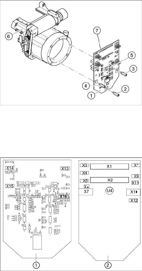
The intermediate distributor (1) is fixed to the front part (6) with four spacer bolts (items 2, 3, 4 and 5).
The cover of the intermediate distributor is fixed with push buttons.
Two 40-pin flat ribbon cables run from plug X1 and X2 on the intermediate distributor to socket X14 / X13
on the head board.
The following supply voltages and signals are routed by the intermediate distributor to the individual
placement head modules or to the head board:
Intermediate distributor
1. Intermediate distributor
2. Spacer bolt M3x10
3. Spacer bolt M3x10
4. Spacer bolt M3x10
5. Spacer bolt M3x10
6. Front section of C&P
7. Connectors X1 and X2 (on the rear side)
Position of the sockets
1. Front of the intermediate distributor
2. Back of the intermediate distributor
U4 = pressure sensor

Description of the Circuit Boards CP12:CP6
SP_12 Digital Intermediate Distributor [00330648-05]
10 Head PCB Overview Step by Step Analysis
Connectors Description
X1, 40-pin Connected to plug X14 on the head board
▪ Voltage supply, tacho and track signals for the Z axis drive
▪ Signal from light barrier "Z axis in top position"
▪ Signal from light barrier "Z axis in bottom position" (sensor stop signal)
▪ Control signal for the blast air valve
▪ Supply voltage +5 VDC, ±15 VDC
▪ Reference point signal for the DP axis
▪ Track signals for the DP axis
X2, 40-pin Connected to plug X13 on the head board
▪ Voltage supply and track signals for the star axis drive
▪ Reference point for the star axis
▪ Analog blast air pressure value
▪ Supply voltages +5 VDC, ±15 VDC, +24 VDC
X3, 10-pin Connection for the Z motor and Z tacho signal (Tacho signal is not use on
the HF machine)
X4, 10-pin Connection for the Z axis track signals
X5, 10-pin Connection for the star motor
X6, 6-pin Connection for the blast air valve
X7, 10-pin Connection for the DP axis track signals
X10, 10-pin Connection for the "Z axis up" signal (positioning unit)
X11, 8-pin Connection for the light barrier "Z axis down" signal (sensor stop signal)
X12, 10-pin Connection for the star axis track signals
X13, 10-pin Test connection for the Z axis track signals
X14, 10-pin not used
X15, 10-pin Test connection for the star axis track signals
X16, 10-pin Test connection for the DP axis track signals
Description of the Circuit Boards PP
Head main board C600
Head PCB Overview Step by Step Analysis 11
3
3 Description of the Circuit Boards PP
Description of the Circuit Boards PP
3.1
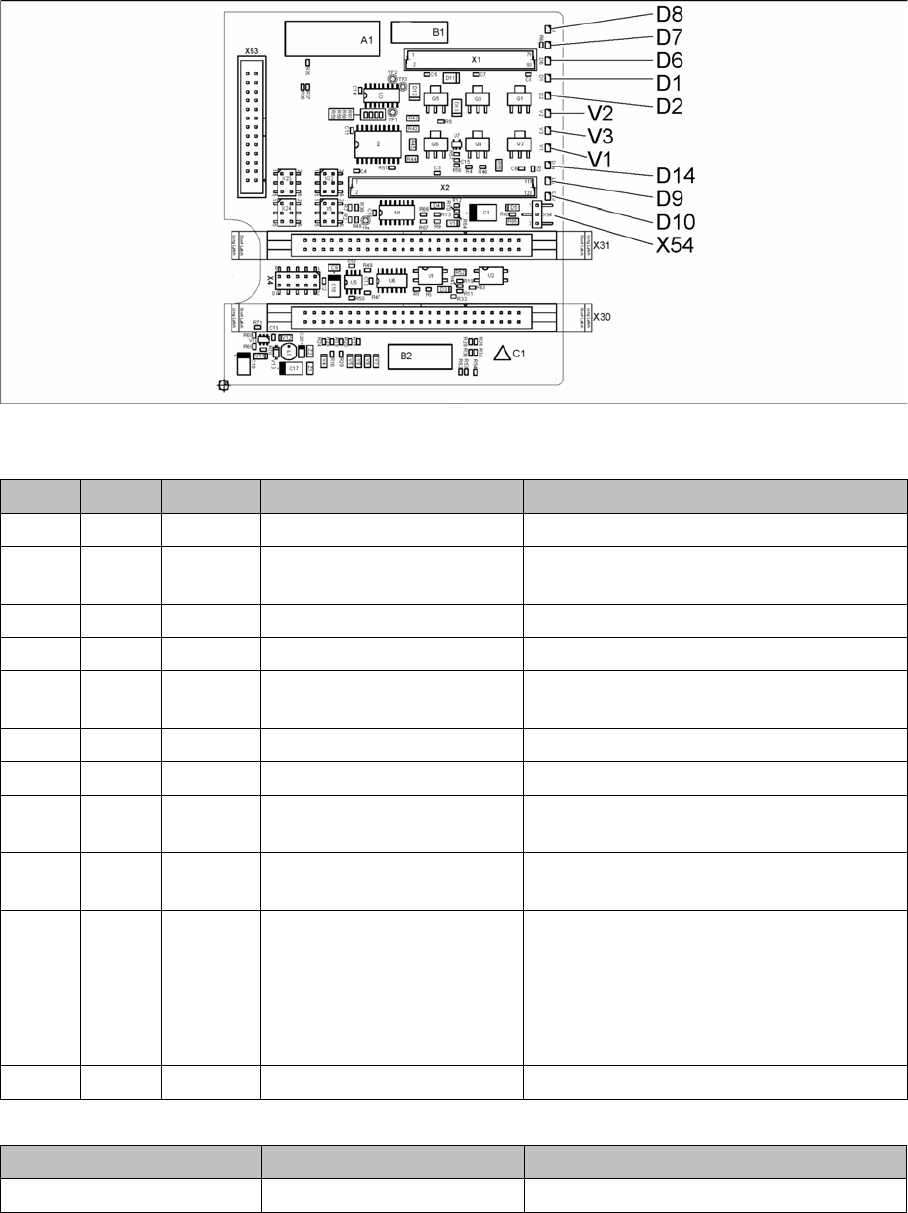
3.1 Head main board C600
Head main board C600
00352833-09
LED [00352833-09]
Jumper [00352833-09]
LED Color Status Signal name Description
D1 YE OFF Z_PRESSURE Not used
D2 YE ON/OFF Z_CLAMPING ON: Z axis clamping activated
OFF: return unit in upper position
D6 GN OFF Z_REFERENCEBERO Not used
D7 GN ON - Return cylinder extended
D8 GN OFF Q3_OUT Flashes shortly when the return unit is ex-
tending
D9 GN OFF Q1_OUT Not used
D10 GN ON VCC_PROPVALVE +24VDC for vacuum generator OK
D14 RD OFF SPI_PROP_VALVE_ALARM
_N
ON: vacuum generator defective
V1 GN ON Z_TEMPERATURESENSO
R
Z motor temperature OK
V2 GN ON/OFF V_OUT Signalizes the 15V power supply for the D
axes track signals
OFF: Jumper X54 set to ON for the old
force measuring board
ON: Jumper X54 set to OFF for the new
force measuring board
V3 GN ON V_OUT +15VDC for the D axes track signals
Jumper Status Description
X54 OFF New force measuring board: LED V2 ON