Head PCB - Overview en - 第11页
Description of the Circuit Boards PP Head main board C600 Head PCB Overview Step by Step Analysis 11 3 3 D e s c r ip t io n o f t h e C ir c u it B o a r d s P P Description of the Circuit Boards PP 3.1 3 . 1 H e a d m …

Description of the Circuit Boards CP12:CP6
SP_12 Digital Intermediate Distributor [00330648-05]
10 Head PCB Overview Step by Step Analysis
Connectors Description
X1, 40-pin Connected to plug X14 on the head board
▪ Voltage supply, tacho and track signals for the Z axis drive
▪ Signal from light barrier "Z axis in top position"
▪ Signal from light barrier "Z axis in bottom position" (sensor stop signal)
▪ Control signal for the blast air valve
▪ Supply voltage +5 VDC, ±15 VDC
▪ Reference point signal for the DP axis
▪ Track signals for the DP axis
X2, 40-pin Connected to plug X13 on the head board
▪ Voltage supply and track signals for the star axis drive
▪ Reference point for the star axis
▪ Analog blast air pressure value
▪ Supply voltages +5 VDC, ±15 VDC, +24 VDC
X3, 10-pin Connection for the Z motor and Z tacho signal (Tacho signal is not use on
the HF machine)
X4, 10-pin Connection for the Z axis track signals
X5, 10-pin Connection for the star motor
X6, 6-pin Connection for the blast air valve
X7, 10-pin Connection for the DP axis track signals
X10, 10-pin Connection for the "Z axis up" signal (positioning unit)
X11, 8-pin Connection for the light barrier "Z axis down" signal (sensor stop signal)
X12, 10-pin Connection for the star axis track signals
X13, 10-pin Test connection for the Z axis track signals
X14, 10-pin not used
X15, 10-pin Test connection for the star axis track signals
X16, 10-pin Test connection for the DP axis track signals
Description of the Circuit Boards PP
Head main board C600
Head PCB Overview Step by Step Analysis 11
3
3 Description of the Circuit Boards PP
Description of the Circuit Boards PP
3.1
3.1 Head main board C600
Head main board C600
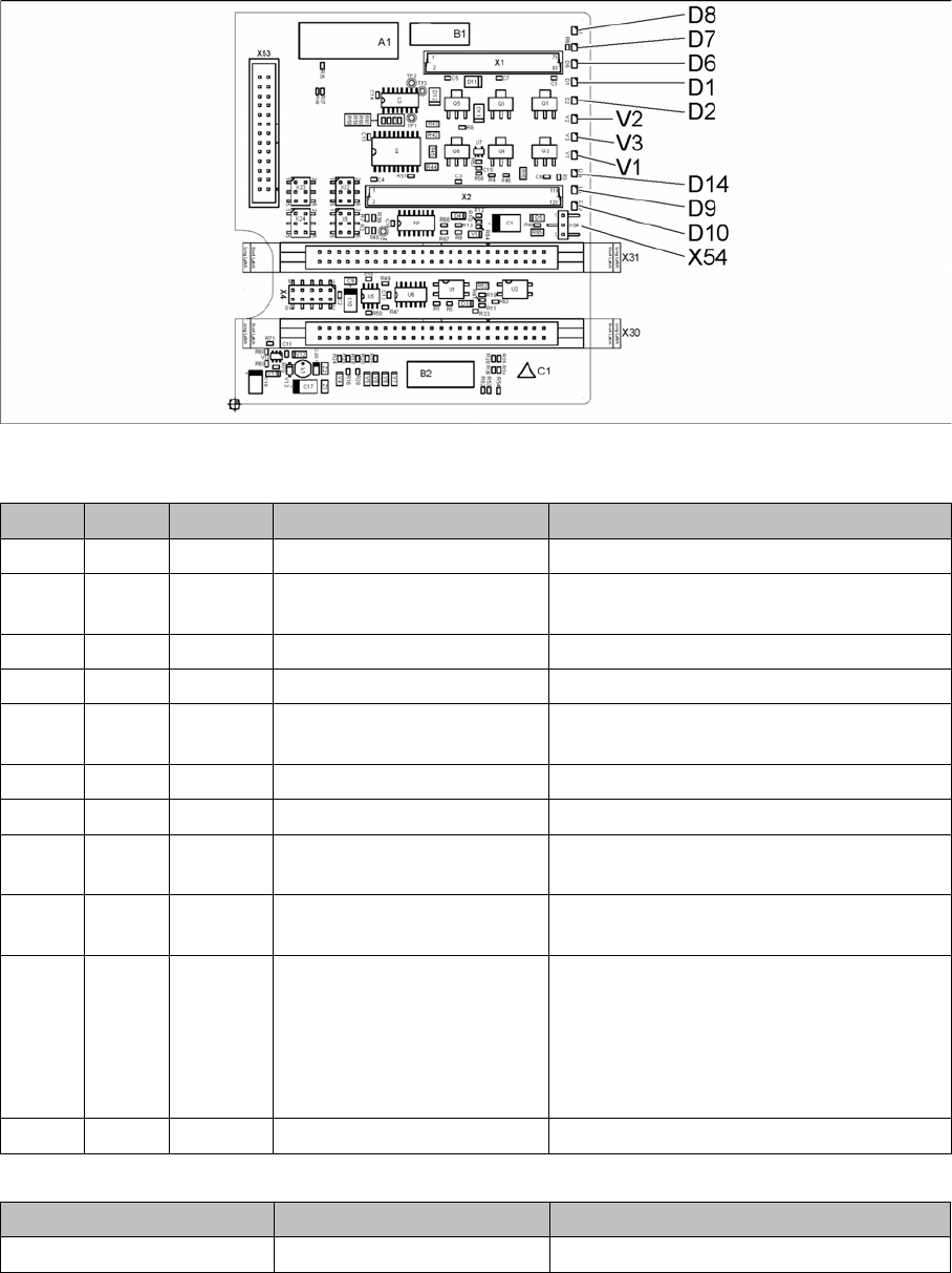
00352833-09
LED [00352833-09]
Jumper [00352833-09]
LED Color Status Signal name Description
D1 YE OFF Z_PRESSURE Not used
D2 YE ON/OFF Z_CLAMPING ON: Z axis clamping activated
OFF: return unit in upper position
D6 GN OFF Z_REFERENCEBERO Not used
D7 GN ON - Return cylinder extended
D8 GN OFF Q3_OUT Flashes shortly when the return unit is ex-
tending
D9 GN OFF Q1_OUT Not used
D10 GN ON VCC_PROPVALVE +24VDC for vacuum generator OK
D14 RD OFF SPI_PROP_VALVE_ALARM
_N
ON: vacuum generator defective
V1 GN ON Z_TEMPERATURESENSO
R
Z motor temperature OK
V2 GN ON/OFF V_OUT Signalizes the 15V power supply for the D
axes track signals
OFF: Jumper X54 set to ON for the old
force measuring board
ON: Jumper X54 set to OFF for the new
force measuring board
V3 GN ON V_OUT +15VDC for the D axes track signals
Jumper Status Description
X54 OFF New force measuring board: LED V2 ON
Description of the Circuit Boards PP
Head main board C600
12 Head PCB Overview Step by Step Analysis
Further Information
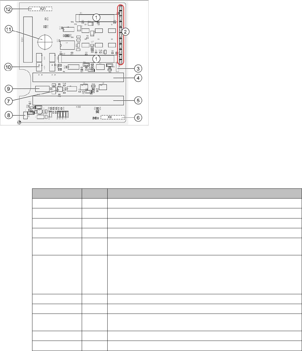
To (2) LEDs (description sequence downwards):
P&P head main board [00352833-xx]
The main board is mounted directly on the P&P head.
This board is connected to the base adapter (SX/DX se-
ries) or the head adapter (X series) via two flat ribbon ca-
bles.
1. 2 connectors for the 16 bit CAN bus processor (not
used for X/D1/D3)
2. LEDs (see below)
3. X54 Jumper currently set to ON, with the new force
measurement board set to OFF (see LED V2/V_SP)
4. Flat ribbon cable connector to the head adapter
5. Flat ribbon cable connector to the head adapter
6. X8: Flex cable (signals: track signals D axis, motor
voltage Z axis/D axis, Z temperature, SPI bus)
7. EEPROM stores the head specific data (head ex-
change, reference run)
8. Power supply 15 V for the D axis track signals (cur-
rently deactivated via the jumper X54)
9. X4 connector, Z axis track signals
10. Connector pneumatic valve (return unit)
11. Hole for pneumatic hose to the vacuum generator
12. X21 connector for vacuum generator
LED Color Description
D8 Green Off – return unit is extending – LED lights up briefly
D7 CLAMP Green On - display showing that the return cylinder has been extended.
D6 BERO Green Off - without function (previously: proximity switch, Z axis top)
D1 PRESSURE Yellow Off - without function (Z pressure)
D2 CLAMP Yellow On – Z axis clamping
Off – return unit is in top position
V2/V_SP Green Shows the 15 V power supply for the D axis track signals.
Off – when jumper setting is ON and with old force measurement board.
On – when TwinHead has new force measurement board, the 15 V is reg-
ulated on the main board i.e. the jumper must be set to OFF and the LED
is on.
V3 15V_ Green On – 15 V for the D axis track signals
V1 TEMP Green On - Z axis motor temperature is OK
D14 ALARM Red Off - Alarm output for the vacuum generator
On - Vacuum generator defective
D9 PRESSURE Green Off - without function (Z pressure)
D10 24V+ Green On – 24 V for vacuum generator OK