Head PCB - Overview en - 第6页
Description of the Circuit Boards CP14 Vacuum Sensor Holding Circuit Board CP14 6 Head PCB Overview Ste p by Step An alysis
Description of the Circuit Boards CP14
Vacuum Sensor Holding Circuit Board CP14
Head PCB Overview Step by Step Analysis 5
DIP switch
1.3
1.3 Vacuum Sensor Holding Circuit Board CP14
Vacuum Sensor Holding Circuit Board CP14
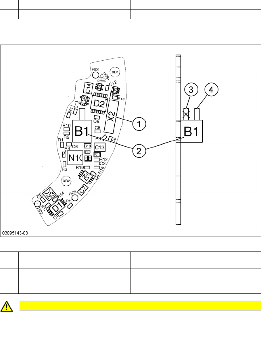
Vacuum sensor holding circuit board CP14
S1 DP Power ON 1-4 OFF
S1 Z down test 2-3 OFF
1 Plug X2 (to intermediate distributor) 2 Pressure sensor (holding circuit/aperture
ring)
3 Bottom hose connection on pressure sen-
sor
→ Do not use!
4 Top hose connection on pressure sensor
CAUTION
Only use the top hose connection
The bottom hose connection (3) directly above the board must remain free.
► Only use the top hose connection (4).
Description of the Circuit Boards CP14
Vacuum Sensor Holding Circuit Board CP14
6 Head PCB Overview Step by Step Analysis
Description of the Circuit Boards CP12:CP6
Base adapter DLM
Head PCB Overview Step by Step Analysis 7
2
2 Description of the Circuit Boards CP12:CP6
Description of the Circuit Boards CP12:CP6
2.1
2.1 Base adapter DLM
Base adapter DLM
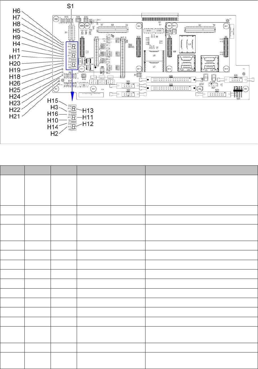
03081413-03
LED [03081413-03]
LED Color Status Signal name Description
H1 RD ON POWERFAIL_LOCAL_N „LOC“-PowerFail board:
ON, when 1.5VDC, 3.3VDC, 5VDC and
15VDC are outside the permissible toler-
ance
H2 RD ON V_DISP_XC167 XC167 error
H3 RD ON V_DISP_HCU1 HCU1 error
H4 RD ON FPGA_TEST_5 24VDC PowerFail:
when voltage < 23VDC
H5 RD ON FPGA_TEST_1 15VDC PowerFail
H6 RD ON FPGA_TEST_6 1.5VDC PowerFail
H7 RD ON FPGA_TEST_2 3.3VDC PowerFail
H8 RD ON FPGA_TEST_4 5VDC PowerFail
H9 RD ON FPGA_TEST_3 Not used
H10 RD ON V_DISP_HCU2 HCU2 error
H14 GN ON V_DISP_XC167 XC167 OK
H15 GN ON F_DISP_HCU1 HCU1 OK
H16 GN ON V_DISP_HCU2 HCU2 OK
H17 RD ON +V-LS Overcurrent display or switching off the light
barriers on the stepping motor
H18 RD ON DZS ERR Overcurrent, „Swivel in“ stepping motor
H19 RD ON ZHS ERR Overcurrent, "Pick-up/placement circuit"
stepping motor