SIPLACE 80 F4_EN.pdf - 第14页
13 Restric tions for Bar Code Re ading of PCB S izes 460 x 460 m m Description S S S Si i i in n n ng g g gl l l le e e e c c c co o o on n n nv v v ve e e ey y y yo o o or r r r The SIPLA CE PCB bar code scan- ner suppo…
12
Description
Due to the increasing use of ce-
ramic substrates in Flip Chip tech-
nology the demands for precise
substrate centering are growing.
The optical and mechanical ce-
ramic substrate centering units on
the SIPLACE 80 S-20 and SIPLACE
80 F
4
placement systems satisfy
these demands.
Like the PCB vision module, opti-
cal centering is conducted with the
aid of reference marks (fiducials).
Depending on the contrast ratio
the machine activates the standard
lighting or the oblique lighting con-
tained in the option:
On ceramic and CM blue light
(Item No 116172).
On flexible PCBs using vision
module without IF-filter infrared
light (Item No 116173).
In certain cases, mechanical cen-
tering is required, e.g., when
placement is to continue to the
substrate edge, when handling of
the edges of the substrate is to be
particularly gentle, or when sub-
strates are scribed. In this gentle,
bounce-free procedure, the sub-
strate is fixed in place in the Y-
direction between a stop rail and a
rocking lever pneumatically cen-
tered in the X-direction.
PCB Conveyor:
Ceramic Substrate Centering (Option)
Technical Data
Substrate dimensions 2" x 2" to 4" x 7"
Substrate thickness 0.5 to 1.5 mm
Substrate model
Unscribed (no difficulty)
Scribed (after test)
Contact in conveyor 2.5 mm
Optical centering:
Field of view of the PCB
vision module
Type of lighting
with light-colored pastes
with dark pastes and short di-
stance to neighboring structu-
res (>1 mm)
5.7 x 5.7 mm
PCB vision module (standard)
Oblique lighting (option)
Fiducal mark criteria
See PCB vision module position reco-
gnition
Mechanical centering
X-/Y-centering accuracy
± 0.07 mm / 4 σ
PCB underside clearance 12 mm
Compressed air connection 5.5 bar
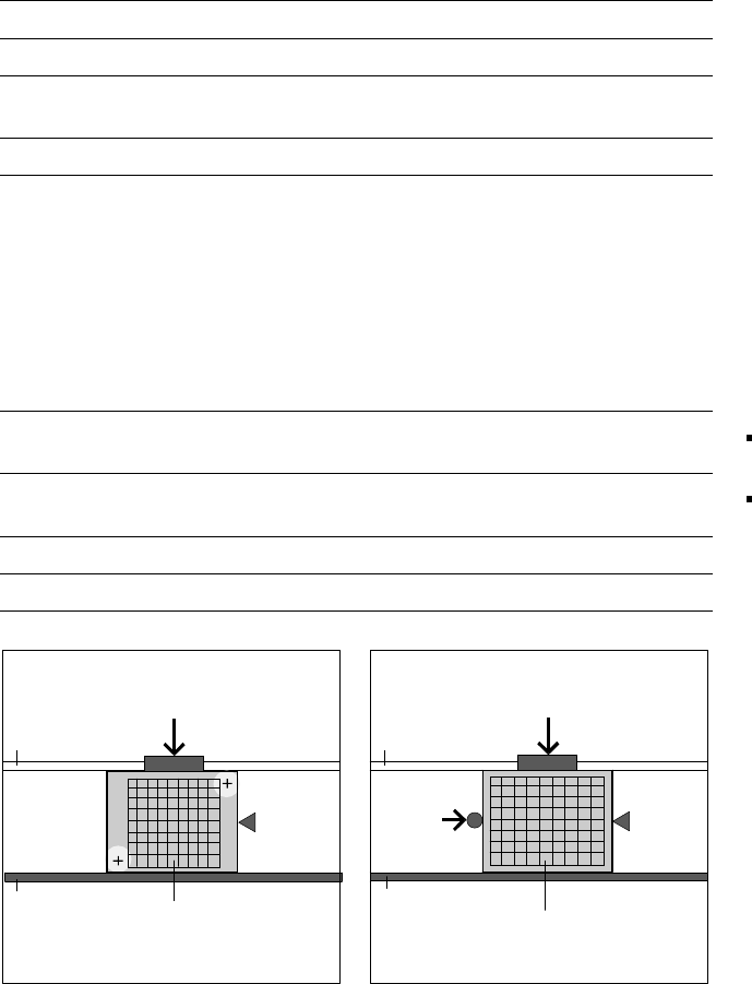
Optical Centering via Mechanical Centering
PCB Camera
Movable
Transport Side
Y-Fixation
Y-Fixation
Fixed
Transport
Side
Fixed
Transport
Side
Stopper
Stopper
Ceramic Substrate
Ceramic Substrate
Movable
Transport Side
X-Center-
ing
13
Restrictions for Bar Code Reading
of PCB Sizes 460 x 460 mm
Description
S
SS
Si
ii
in
nn
ng
gg
gl
ll
le
e e
e c
cc
co
oo
on
nn
nv
vv
ve
ee
ey
yy
yo
oo
or
rr
r
The SIPLACE PCB bar code scan-
ner supports the flexible produc-
tion of SMD products and en-
hances placement reliability. It
recognizes all code types in gen-
eral use for industrial applications.
The laser scanner reads the bar
code label on the top and/or bot-
tom of each PCB moving during
transport. On the basis of the bar
code information the line computer
automatically selects the correct
placement program from the pre-
viously prepared bar code assign-
ment list and sends it to the sta-
tion. This procedure is performed
in slack time while a PCB already
in the placer is being populated. If
a number of PCBs with the same
bar code are moved in one after
the other, the program is only
transferred the first time. The fol-
lowing preconditions apply for all
products which are to be manufac-
tured with the aid of the PCB bar
code:
identical component set-up at
the individual machines in the
line
all PCBs of same width.
The bar code filter can be utilized,
if only certain information con-
tained in the bar code is relevant.
D
DD
Du
uu
ua
aa
al
l l
l c
cc
co
oo
on
nn
nv
vv
ve
ee
ey
yy
yo
oo
or
rr
r
With a dual conveyor, the sole
purpose of the PCB bar code is to
relay the bar code via a GEM inter-
face. This is imperative for utiliza-
tion. Automatic placement pro-
gram supply is not possible.
PCB Conveyor:
PCB Bar Code for Production-Controlled Manufacturing (Option)
Technical Data
Max. PCB size
Single conveyor
Standard: (L x W) to 460 x 460 mm
Optional: (L x W) to 508 x 460 mm
(same width in all jobs of a run)
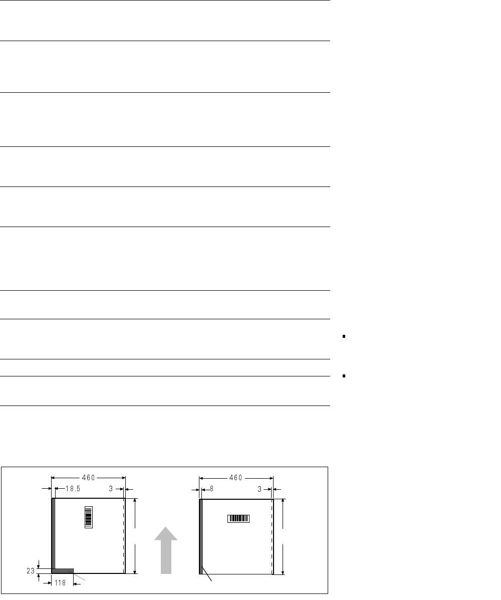
Bar-code-free PCB edge
3 mm on left and right parallel to PCB
transport direction (the additional restricti-
ons shown in figure at the bottom apply
for scanning the bar code from above)
Label dimensions
Stroke width: W: 0.19 < W ≤ 0.3 mm
(corresponds to high + medium density)
Stroke length: ≥ 4 mm*
Length of scanning window: ≤ 90 mm
Label alignment on PCB**
Parallel or at right angles to the PCB
transport direction, preferably next to
fixed conveyor side
Recommended label colors
(contrast ratio > 70%
as per DIN 66236)
Color coding: black, dark green or dark
blue
Background: white, beige, yellow, orange
Code types
Code 39, Code 128 / EAN 128,
Codabar, 2/5 IATA 2/5 industrial,
2/5 interleaved, UPC, EAN,
Pharma Code, EAN Addendum
(more upon request)
Complete bar code
Max. 25 characters
Definition of a bar code filter possible
Safety of the laser scanner
Laser diode 670 nm (red) / 1 mW
Laser protection class 2, degree of protec-
tion IP65
Station and line software from Version 401.xxx
Scan-in/analysis time
Slack time (T ≤ 1 s), as parallel to the pla-
cement of preceding PCB
* This value can only be met if the bar code label on the PCB moves through the bar code scanner at
right angles to the machine’s direction of transport.
** Depending on where the bar code label is located on the PCB, the position of the bar code scanner
can be easily adjusted in the input conveyor belt.
restricted
restricted
PCB
Transport
Direction
460
460
14
Description
SIPLACE 80 F
4
is equipped with
two stationary component feed-
ers, one on the left and one on the
right of the PCB conveyor. As
standard there is a component
changeover table on the left. As
options, either a tray changer with
a narrow component table or an-
other changeover table can be
placed on the right. With two
component changeover tables the
total capacity is, e.g., 2 x 40 tape
tracks of 8 mm each.
The component feeders are sta-
tionary during the placement proc-
ess, therefore it is possible to refill
components (e.g., in sticks) or
splice tapes without stopping the
machine.
For a changeover, either individual
feeders or the entire changeover
table can be exchanged without
any tools for component tables set
up outside the placer.
Use of component bar codes with
the aid of an optional component
bar code scanner guarantees the
correct assignment of the compo-
nent to the track.
To make full use of the advantages
of the component changeover ta-
ble, the entire set-up including the
check can also be conducted out-
side the machine at the optional
SIPLACE set-up station. The
changeover tables are transported
with a lift cart in this case. Ex-
changing the tables takes about
2 minutes per module.
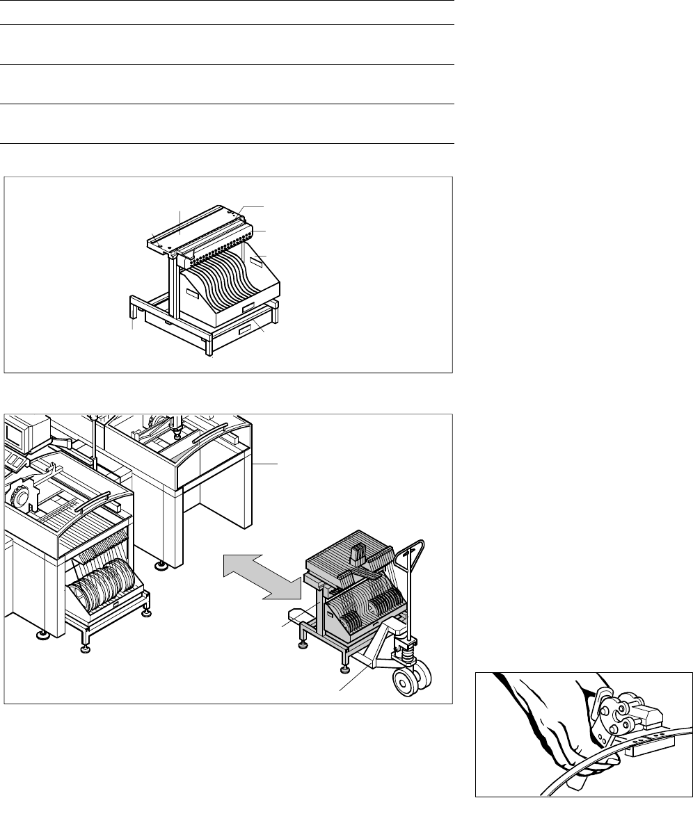
Component Supply:
Changeover Table
Technical Data
Insert (exchangeable) In all SIPLACE placement modules
Feeder locations
20 x 8 mm dual track per table =
40 x 8 mm tracks, 2 tables per machine
Feeder modules
SIPLACE feeders for tapes,
stick magazines, Bulk Cases
Accessories
Tape container, waste container, lift cart
empty table cutter
Exchange of a Feeder Changeover Table
Construction of a Changeover Table
Pallet Jack
Basic Frame
Feeder Table
Centering Position
SIPLACE Station
Changeover Table
Compressed Air
Feeder Connection
Reel Container
Re
j
ect Bin
Splicing Tool