SIPLACE 80 F4_EN.pdf - 第22页
21 Description The component changeov er tables can be s et up and checke d at an external SIPLACE set-up station quickly and witho ut mac hine idle time. The costs for production in- volving a great variety of c ompo- n…
20
Description
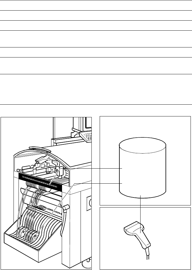
The bar code scanner enables a
speedy and reliable check of set-
up and refill. To this end the bar
codes of the tracks (on the track
scale on the component table) and
the loaded components assigned
to the tracks (bar code labels on
tapes, Bulk Cases, etc.) are read in
with a hand scanner. An audible
and optical signal acknowledges a
successful reading operation. If the
label is damaged the bar can also
be entered at the keyboard.
The allocation of the components
to their respective track is de-
scribed in the set-up data. An error
message is displayed if the data
received from the bar code scan-
ner does not conform with the set-
up data.
If the set-up check is switched on,
it becomes a mandatory step in
the set-up process. If it is
switched off the set-up check is
optional.
Component Supply:
Component Bar Code Scanner for Set-Up and Refill Check
(Option)
Technical Data
Connection Station computer
Data input Bar code scanner or keyboard
Max. number of characters 40
Restrictions
Bar codes beginning with number 1 or 2
or with less than 5 characters
Number of bar codes 6 per component
Number of filters
to extract relevant data 1 per bar code
Preset code types
Code 39 (standard or full ASCII),
Code 2 from 5 interleaved and normal,
Code 128, UPC/EAN/JAN codes
(more on request)
The scanner checks the corresponding track and
the components
Component
Control
Set-Up File
Track Bar Code
Scanner
Component
Bar Code
21
Description
The component changeover tables
can be set up and checked at an
external SIPLACE set-up station
quickly and without machine idle
time. The costs for production in-
volving a great variety of compo-
nents are greatly reduced. During
the bar code check outside the
machine, 10 minutes of machine
standstill are eliminated per set-up
change. All current data from up to
4 lines are accessible over a link to
the line computer via a Local Area
Network (LAN).
In the case of the SIPLACE 80 F
4
a component changeover table is
part of the standard equipment.
Additional changeover tables are
required for optimal use of the set-
up station.
Component Supply:
SIPLACE External Set-Up Station (Option)
Technical Data
Operating system Windows NT 4.0
Set-up check Per bar code scanner
Component table change Time expanded: 2 min / table side
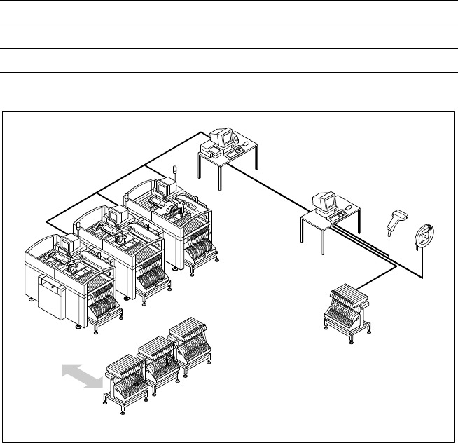
Example for SIPLACE set-up station
Line
LAN
Line Computer
PC for External set-up
LAN Scanner
Serial Interface
Tape Reel
with
Bar Code
Changeover
Table
Component Changeover Tables
22
Description
With the SIPLACE 80 F
4
a number
of vision modules with a central vi-
sion system to evaluate the re-
corded image data ensure a high
placement accuracy.
At the machine’s X-gantry the PCB
vision module finds position off-
sets on the part of the PCB in the
conveyor system. This module is
also required to measure the ma-
chine and/or the feeders on one
side of the table. This vision mod-
ule consists of a single CCD cam-
era with integrated lighting and op-
tics.
The offsets in the position of the
PCBs are determined with the
help of at least two but generally
three reference fiducial marks on
the PCB. When the PCB arrives
the gantry with its PCB vision
module moves to the programmed
mark position. The vision system
compares the recorded video im-
age with the sample stored in the
PCB description.
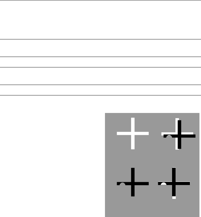
With the help of the correlation
principle the vision system can de-
termine the correct position even
when fiducial marks are incom-
plete or damaged (actual struc-
tures). It does so by making com-
parisons with programmed
nominal structures. The mark con-
figurations are not fixed; they can
be taught without restriction.
Additional functions of the PCB vi-
sion module are recognition of the
position of the feeders and ce-
ramic substrate (optional) and re-
cording of the machine data in-
cluding mapping.
In addition, the bad board recogni-
tion unit is moved over “ink spots”
with the aid of the PCB vision
module.
Vision Sensor Technology:
PCB Vision Module
Technical Data
Reference marks
Local marks
Library memory
Recognition of poor panels
up to 3 (subpanels and multiple panels)
up to 2 per component
(may be of different type)
up to 255 types of reference marks
per subpanel
Image processing
Correlation principle based on
gray values
Illumination Front light
Recognition time
mark/ink spot 0.8 s
Camera’s field of view 5.7 x 5.7 mm
Correlation Principle
Target Low
Structure Correlation
Actual High
Structure Correlation