SIPLACE 80 F4_EN.pdf - 第32页
31 Description P P P Pl l l la a a ac c c ce e e em m m me e e en n n nt t t t R R R Re e e eli li li lia a a ab b b bili ili ili ilit t t ty y y y Aside from correct positi oning, placement reliabilit y also means a gen…
30
Description
Various factors contribute to the
placement accuracy of the
SIPLACE 80 F
4
machine, e.g., the
stationary PCB during the place-
ment process. As no accelerations
are acting on the placed compo-
nents, their position continues un-
changed. The PCB moves in and
out at a coordinated speed which
is automatically reduced just be-
fore the nominal position is
reached.
A further guarantee for long-term
high placement accuracy is the
position recognition of the axes of
the gantry and placement head by
means of optical scanning by in-
cremental encoders. Revolving
star and segments of the revolver
head are positioned by means of
high-resolution glass incremental
panels. The X- and Y-axes are posi-
tioned with the help of the metal
scales on each gantry axis.
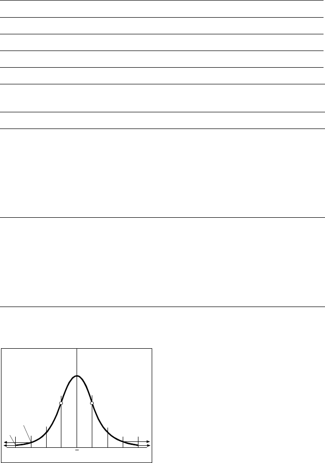
To determine the placement accu-
racy on SIPLACE machines, highly
precision glass components with
mounted structures are placed on
a dimensionally accurate glass
mapping plate. The results are sta-
tistically evaluated and presented
as a Gaussian standard distribu-
tion. In the case of the 12-nozzle
revolver head the placement accu-
racy is ± 90 µm at a statistical reli-
ability of 4 sigma. In other words,
of one million placed components,
60 are outside the specified toler-
ance (= 60 dpm). If the accuracy
value ± 90 µm is divided by the
sigma value 4, the result is the
standard deviation S of 1 sigma =
± 22.5 µm.
A machine capability analysis is
conducted for each machine ac-
ceptance test.
Machine Criteria:
Placement Accuracy
Technical Data Gantry
Drive DC servomotors
Position measuring system (X/Y) Linear scales
Resolution of X-/Y-axis 2.5 µm
Speed of X-axis max. 2 m/s
Speed of Y-axis max. 2.5 m/s
Accuracy
X-/Y- and D-axis offset in optical component and PCB centering
12-nozzle revolverhead
Angle accuracy
Placement accuracy
± 0.525° / 3 σ
± 0.70° / 4 σ
± 1.05° / 6 σ
± 67.5 µm/ 3 σ
± 90 µm/ 4 σ
± 135 µm/ 6 σ
Pick & Place-head
Angle accuracy
Placement accuracy
± 0.052° / 3 σ
± 0.07° / 4 σ
± 0.105° / 6 σ
± 37.5 µm/ 3 σ
± 50 µm/ 4 σ
±75 µm/ 6 σ
Standard Deviation - dpm
-4
σ
-3
σ
-2
σσ
x
σ
2
σ
3
σ
4
σ
2700 dpm
60 dpm
P Point of Inflection
31
Description
P
PP
Pl
ll
la
aa
ac
cc
ce
ee
em
mm
me
ee
en
nn
nt
t t
t R
RR
Re
ee
eli
lili
lia
aa
ab
bb
bili
iliili
ilit
tt
ty
yy
y
Aside from correct positioning,
placement reliability also means a
gentle handling of the compo-
nents, so that these can be sol-
dered well later. Rework is mini-
mized or eliminated as a result.
On the SIPLACE 80 F
4
among
others this is ensured through a
number of control functions, e.g.,
the vacuum checks and compo-
nent vision test during the revolver
head sequence.
Unsuitable components are re-
jected, placed on the repair list and
automatically processed during a
repair cycle. An offset in the posi-
tion of the PCB relative to the con-
veyor system (PCB vision) and an
offset of the X-axis, Y-axis or rota-
tion of the component relative to
the midpoint of the nozzle (com-
ponent vision) trigger an immedi-
ate correction and thus placement
accuracy.
Thanks to the motionless PCB the
components remain in the exact
position they were placed. The
stationary component table pro-
tects, for example, the compo-
nents in Bulk Cases against dam-
age such as may occur due to
vibrations which are inevitable with
other placement concepts. Op-
tional add-on products ensure fur-
ther reliability: With the aid of the
component bar code scanner, the
correct placement program is
automatically sent to the station.
P
PP
Pi
ii
ic
cc
ck
kk
k-
--
-u
uu
up
p p
p e
ee
er
rr
rr
rr
ro
oo
or
rr
rs
ss
s
All errors which occur between the
time the component is picked up
and the time it is placed on the
PCB are pick-up errors. They in-
clude:
No component in the tape
Component cannot be removed
from the tape.
Vacuum error
Vision error due to faulty com-
ponent
Vision error due to unrecognized
component
P
PP
Pl
ll
la
aa
ac
cc
ce
ee
em
mm
me
ee
en
nn
nt
t t
t e
ee
er
rr
rr
rr
ro
oo
or
rr
rs
ss
s
Errors which occur after the com-
ponent has been placed on the
PCB. They include:
Rotation error
Too many components on PCB
X/Y-offset
P
PP
Pl
ll
la
aa
ac
cc
ce
ee
em
mm
me
ee
en
nn
nt
t t
t S
SS
Sp
pp
pe
ee
ee
ee
ed
dd
d
When used alone on the SIPLACE
80 F
4
the 12-nozzle revolver head
achieves a benchmark placement
rate of 10,000 components per
hour (cph). The Pick & Place head
places at a max. speed of 1,800
cph. These benchmark rates can
be verified on the demonstration
PCB at Siemens.
Factors such as PCB size, number
of components per board and their
layout have a certain effect on the
speed in actual practice. The
placement speed in practice can
be predicted using a calculation
program.
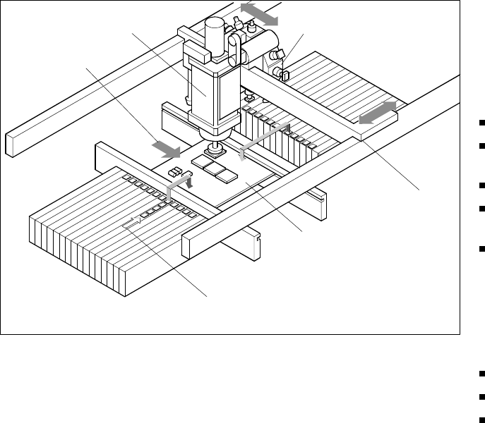
Machine Criteria:
Placement Reliability and Placement Speed
Placement Principle SIPLACE 80 F
4
Pick & Place Head
PCB Transport
Direction
Revolver Head
X/Y-Gantry
System
Fixed PCB
Fixed Component
Su
pp
l
y
32
Description
Despite the highly stable machine
frame, slight distortions of the
gentry axes cannot always be
avoided. With the aid of the map-
ping process the high placement
accuracy of the machine is pre-
served throughout its entire serv-
ice life.
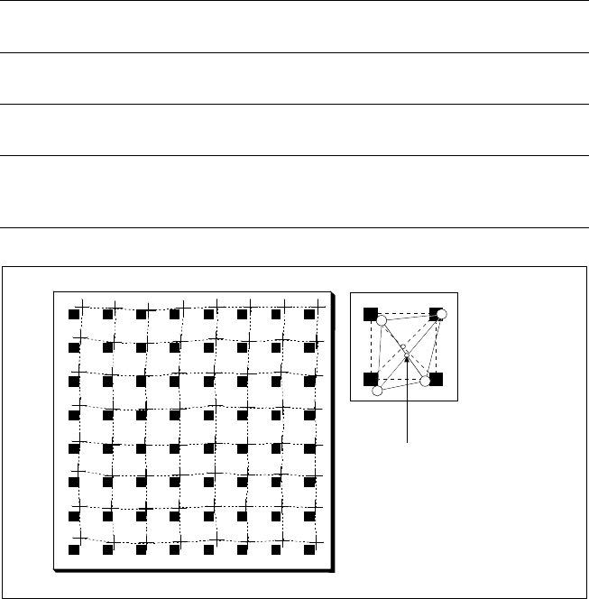
With this calibrating procedure,
which can be conducted quickly
and easily, the PCB camera recog-
nizes the fiducials on a mapping
calibration plate placed in its oper-
ating area. Any distortions are re-
vealed by comparing the nominal
grid on the glass plate with the ac-
tual grid “drawn” by placement
head. These distortions are taken
into account during all further posi-
tioning of X-/Y-axes and thus com-
pensated for.
Machine Criteria:
Mapping (Option)
Technical Data
Dimensions of the mapping
test plate
520 x 460 mm (for single conveyor)
520 x 215 mm (for dual conveyor)
Number of measurement
points
13 x 11 (standard resolution)
26 x 21 (high resolution)
Ambient temperature during
calibration + 20° ± 3°C
Components of the option
Test plate (special glass)
Calculation data (disk)
Case for secure storage
Nominal Grid of Mapping Plate and Actual Grid with
Deviations Due to Gantry
Corrected
Position