SIPLACE 80 F4_EN.pdf - 第33页
32 Description Despite the hi ghly st able ma chine frame, slight distortions of the gentry axes cannot alway s be avoided. With the aid of the ma p- ping process the high placement accuracy of the machin e is pre- serve…
31
Description
P
PP
Pl
ll
la
aa
ac
cc
ce
ee
em
mm
me
ee
en
nn
nt
t t
t R
RR
Re
ee
eli
lili
lia
aa
ab
bb
bili
iliili
ilit
tt
ty
yy
y
Aside from correct positioning,
placement reliability also means a
gentle handling of the compo-
nents, so that these can be sol-
dered well later. Rework is mini-
mized or eliminated as a result.
On the SIPLACE 80 F
4
among
others this is ensured through a
number of control functions, e.g.,
the vacuum checks and compo-
nent vision test during the revolver
head sequence.
Unsuitable components are re-
jected, placed on the repair list and
automatically processed during a
repair cycle. An offset in the posi-
tion of the PCB relative to the con-
veyor system (PCB vision) and an
offset of the X-axis, Y-axis or rota-
tion of the component relative to
the midpoint of the nozzle (com-
ponent vision) trigger an immedi-
ate correction and thus placement
accuracy.
Thanks to the motionless PCB the
components remain in the exact
position they were placed. The
stationary component table pro-
tects, for example, the compo-
nents in Bulk Cases against dam-
age such as may occur due to
vibrations which are inevitable with
other placement concepts. Op-
tional add-on products ensure fur-
ther reliability: With the aid of the
component bar code scanner, the
correct placement program is
automatically sent to the station.
P
PP
Pi
ii
ic
cc
ck
kk
k-
--
-u
uu
up
p p
p e
ee
er
rr
rr
rr
ro
oo
or
rr
rs
ss
s
All errors which occur between the
time the component is picked up
and the time it is placed on the
PCB are pick-up errors. They in-
clude:
No component in the tape
Component cannot be removed
from the tape.
Vacuum error
Vision error due to faulty com-
ponent
Vision error due to unrecognized
component
P
PP
Pl
ll
la
aa
ac
cc
ce
ee
em
mm
me
ee
en
nn
nt
t t
t e
ee
er
rr
rr
rr
ro
oo
or
rr
rs
ss
s
Errors which occur after the com-
ponent has been placed on the
PCB. They include:
Rotation error
Too many components on PCB
X/Y-offset
P
PP
Pl
ll
la
aa
ac
cc
ce
ee
em
mm
me
ee
en
nn
nt
t t
t S
SS
Sp
pp
pe
ee
ee
ee
ed
dd
d
When used alone on the SIPLACE
80 F
4
the 12-nozzle revolver head
achieves a benchmark placement
rate of 10,000 components per
hour (cph). The Pick & Place head
places at a max. speed of 1,800
cph. These benchmark rates can
be verified on the demonstration
PCB at Siemens.
Factors such as PCB size, number
of components per board and their
layout have a certain effect on the
speed in actual practice. The
placement speed in practice can
be predicted using a calculation
program.
Machine Criteria:
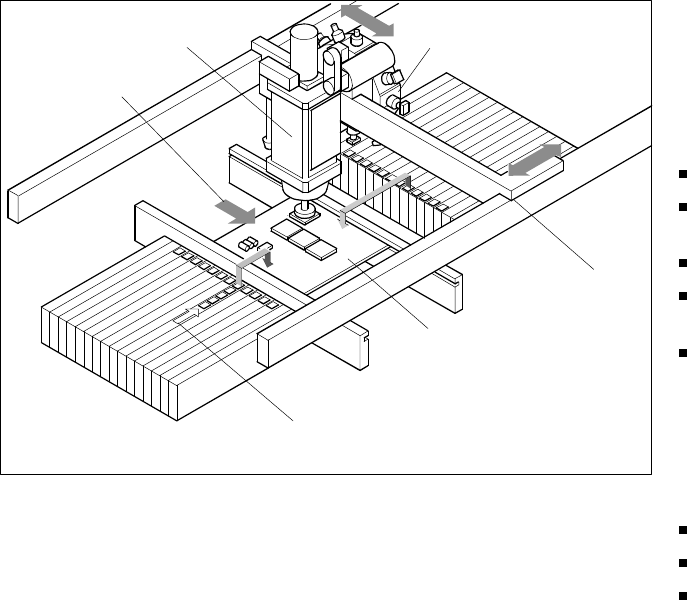
Placement Reliability and Placement Speed
Placement Principle SIPLACE 80 F
4
Pick & Place Head
PCB Transport
Direction
Revolver Head
X/Y-Gantry
System
Fixed PCB
Fixed Component
Su
pp
l
y
32
Description
Despite the highly stable machine
frame, slight distortions of the
gentry axes cannot always be
avoided. With the aid of the map-
ping process the high placement
accuracy of the machine is pre-
served throughout its entire serv-
ice life.
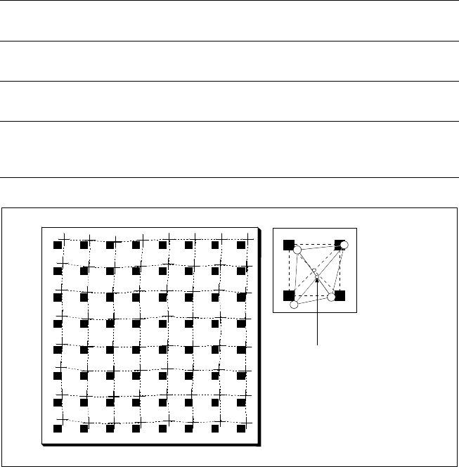
With this calibrating procedure,
which can be conducted quickly
and easily, the PCB camera recog-
nizes the fiducials on a mapping
calibration plate placed in its oper-
ating area. Any distortions are re-
vealed by comparing the nominal
grid on the glass plate with the ac-
tual grid “drawn” by placement
head. These distortions are taken
into account during all further posi-
tioning of X-/Y-axes and thus com-
pensated for.
Machine Criteria:
Mapping (Option)
Technical Data
Dimensions of the mapping
test plate
520 x 460 mm (for single conveyor)
520 x 215 mm (for dual conveyor)
Number of measurement
points
13 x 11 (standard resolution)
26 x 21 (high resolution)
Ambient temperature during
calibration + 20° ± 3°C
Components of the option
Test plate (special glass)
Calculation data (disk)
Case for secure storage
Nominal Grid of Mapping Plate and Actual Grid with
Deviations Due to Gantry
Corrected
Position
33
Description
The control software is coordi-
nated with the modular architec-
ture of the SIPLACE production
line. It is based on a high-level real-
time multitasking operating sys-
tem which is optimally suited for
the control of time-critical proc-
esses in the placement machine.
Window technology and Touch-
Screen operator interface facilitate
handling with the line and station
computers which cooperate
closely in dividing the tasks to be
performed. The context-sensitive
on-line information and help sys-
tem comments on current events
in writing and graphics, for exam-
ple, and offers short information
about button in the toolbar or in
menu entries.
The UNIX multitasking operating
system of the line computer
makes it possible to perform more
than one work sequence at a time.
While the population of a PCB is in
process, for example, it is already
possible to determine the opti-
mized layout of the feeders for the
next PCB type (set-up optimiza-
tion). It is also possible to edit in
several windows or to look into the
MDA/PDA data without affecting
the placement speed. When pro-
duction planning is physically and
organizationally separate from the
production department, it is advis-
able to use a second line computer
as an off-line programming
system.
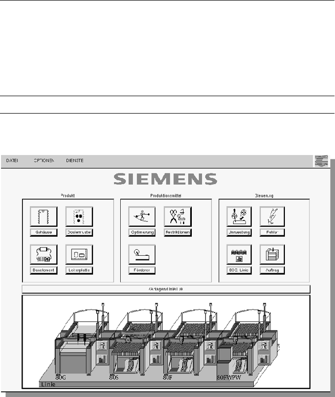
SIPLACE Software Architecture:
System Architecture
Technical Data
Operating system:
Line computer
Station computer
Machine controller
SCO UNIX
®
Microsoft
®
Windows with Touch Screen
RMOS
®
Realtime Multitasking Operating System
Support On-line information and help system
Graphic Operator Environment