SIPLACE 80 F4_EN.pdf - 第39页
38 Description S S S SI I I IP P P PL L L LA A A AC C C CE E E E O O O On n n nl i li li lin n n ne e e e The product Remote Support en- ables online acces s to the line computer, station computer and machine controller …
37
Description
The function of the Semiconductor
Equipment Communication Stan-
dard (SECS) II is the uniform defini-
tion of communication interfaces
to the production equipment ob-
tained from different manufactur-
ers. It has been further developed
into GEM Standard (General
Equipment Model) which is also
suitable for SMT production facili-
ties. To this end, an external user-
specific production computer
(host) is connected via LAN to a
GEM computer integrated into the
machine control. The interface is
used by host systems created by
the user or by application software
from a third-party manufacturer.
The SECS II / GEM communication
protocol supports central control,
process control and their data
management of entire production
lines at the line computer. It is
possible through Statistical Proc-
ess Control (SPC), for example, to
effect preventive maintenance
which eliminates or greatly re-
duces non-productive time.
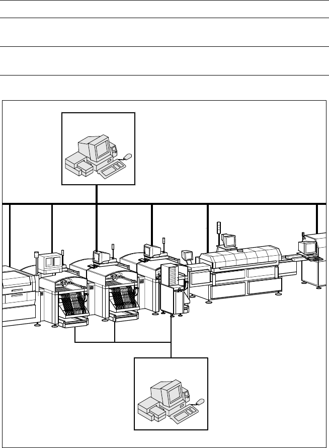
SIPLACE Software Architecture:
Data Interface SECS II / GEM (Option)
Functions
Identification of the equipment
Access to
Product data, error messages,
machine states, measurement results
Protection of
Data, connections
(connection set-up, resynchronization)
Configuration of a Production Line with GEM Computer
HOST
Line Computer
Factory LAN GEM
GEM
GEM
GEM
GEM
38
Description
S
SS
SI
II
IP
PP
PL
LL
LA
AA
AC
CC
CE
E E
E O
OO
On
nn
nli
lili
lin
nn
ne
ee
e
The product Remote Support en-
ables online access to the line
computer, station computer and
machine controller of SIPLACE
placement systems from the sup-
port centers in Munich, Norcross
and Singapore. The SIPLACE ex-
perts in the pertinent support cen-
ter can employ remote data and
the program files of the individual
SIPLACE lines in Production to an-
swer all questions about the
placement systems, immediately
and online.
S
SS
SI
II
IP
PP
PL
LL
LA
AA
AC
CC
CE
E E
E R
RR
Re
ee
em
mm
mo
oo
ot
tt
te
e e
e S
SS
Su
uu
up
pp
pp
pp
po
oo
or
rr
rt
t t
t i
ii
in
nn
n
A
AA
Ac
cc
ct
tt
tu
uu
ua
aa
al
l l
l P
PP
Pr
rr
ra
aa
ac
cc
ct
tt
ti
ii
ic
cc
ce
ee
e
Remote Support is offered on the
basis of communication via ISDN
(Integrated Services Digital Net-
work). Due to its high data trans-
mission speed (64,000 or 128,000
bits/s) ISDN is an ideal medium for
high-speed transfer of large quanti-
ties of data, the SIPLACE expert at
a “Remote Support Position”,
which consists of one line com-
puter, one station computer and a
communications router, can log
himself or herself into the corre-
sponding computers of the
SIPLACE line in the customer's
plant. Remote Support positions
are available in Munich, Norcross
and Singapore. An ISDN router is
also installed at the SIPLACE or
site LAN of the customer. There
need be only one such router per
production facility, however, if the
lines at the customer's site are in-
terconnected via a site LAN.
Basically, the same functionality is
available via Remote Support as is
possible at the local computers
(line computer, station computer
and machine controller).
To comply with the customer's
need for security where sensitive
production data are involved, many
mechanisms (automatic callback,
password protection, switch-off
mode, etc.) are integrated into the
system and can be applied specifi-
cally.
.
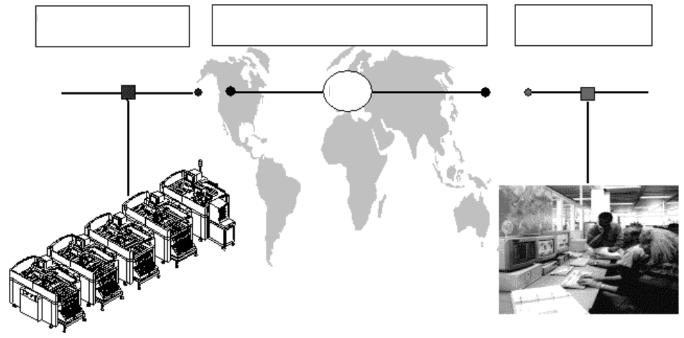
SIPLACE Software Architecture:
Remote Support (Option)
SIPLACE Expert Knowledge Immediately and Round the World
Customer´s production
bay
SIPLACE Support
Station
Public networks / Interfaces
Support LAN
Munich
Norcross
Singapore
Customer LAN
ISDN
39
1. After switching-on the station
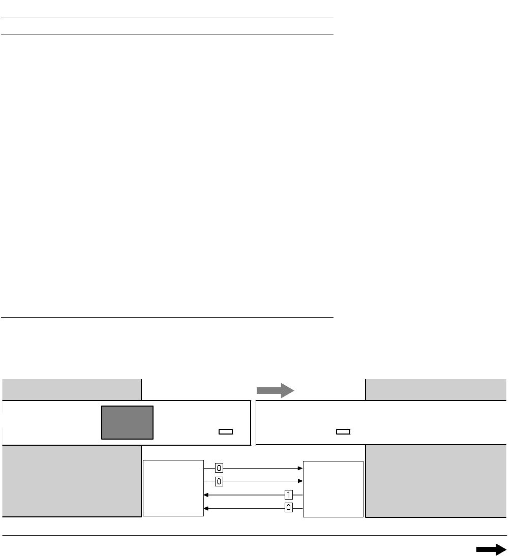
Technical Data:
Signal Interfaces
Signal Interface (20-Pin Ribbon Cable Connector)
to upstream station x3 to downstream station x4
Pin 13 GND 24 V Pin 10 Reserved
Pin 14 Arrived Pin 9 Reserved
Pin 15 Permission Pin 8 Reserved
Pin 19 Request Pin 4
+30 V DC
unsaturated
Pin 20
GND 24 V for request / re-
leased (contact separation)
Pin 5 GND 24 V
Pin 18 Released Pin 6 +24 V DC
Pin 12 Trouble signal loop Pin 11 Trouble signal loop
Pin 11 Pin 12
Pin 3 +24 V DC Pin 15 Permission
Pin 2 GND 24 V Pin 13
GND 24 V for per-
mission / arrived
(contact separation)
Pin 1 +30 V DC unsaturated Pin 14 Arrived
Pin 8 Reserved Pin 18 Released
Pin 9 Reserved Pin 19 Released
Pin 10 Reserved Pin 20 GND 24 V
Requirement
Delivery
Permission
Receival
Requirement
Delivery
Permission
Receival
Transport Direction
Conveyor Section 1
PCB
Sensor
PCB
Sensor
Conveyor Section 2
Station n
transports
PCB
to delivery
Station n+1
is ready to
receive PCBs
Conveyor 1 is On Conveyor 2 is Off