SIPLACE 80 F4_EN.pdf - 第6页
5 Description The main X-/Y-gantry features two placement heads, the 1 2-nozzle high-speed revolver pl acement head and the high-precision P ick & Place head or Fine Pitch place- ment head. With certain overl apping,…

4
Input Station
Screen Printer
Oven
SIPLACE 80 S-20
SIPLACE 80 S-20
SIPLACE 80 F
4
with Waffle Pack Changer
Output
Station
Example of a SIPLACE Placement Line
Description
The modular SIPLACE design is
characterized by flexibility and
adaptability. It permits an individual
production line composition of
similar and different modules.
When performance requirements
change the individual machines
can be recombined quickly and
without complications, one of the
major reasons being their relatively
small size.
The SIPLACE family offers the
right product for each purpose -
from high-speed SMD placement
systems SIPLACE 80 S-20 to the
flexible Fine-Pitch placement
system SIPLACE 80 F
4
.
SIPLACE 80 F
4
is ideally suited for
fixed set-up as well as for family
set-up with optimized changeover
times. When the required capacity
is low, however, it is also suitable
as a standalone placement sys-
tem.
Line Design
Technical Data
System SIPLACE SMD placement lines
Modules
SIPLACE 80 S-20 / SIPLACE 80 F
4
/
SIPLACE HS-50 / SIPLACE S-23 HM /
SIPLACE F
5
Peripherals
Input/output station, screen printer,
solder oven, inspection conveyor etc.,
available from Siemens
Component range 0201* to 55 x 55 mm**
PCB conveyor
PCB dimensions
Ceramic substrate dimensions
Automatic width adjustment
50 x 50 mm to 460 x 460 mm
(optional 460 x 508 mm)
2" x 2" to 4" x 7"
Placement speed depends on layout of modules
Space required
4 m² / SIPLACE S & F modules
7.5 m² / SIPLACE HS module
* Collect & Place
** Pick & Place
5
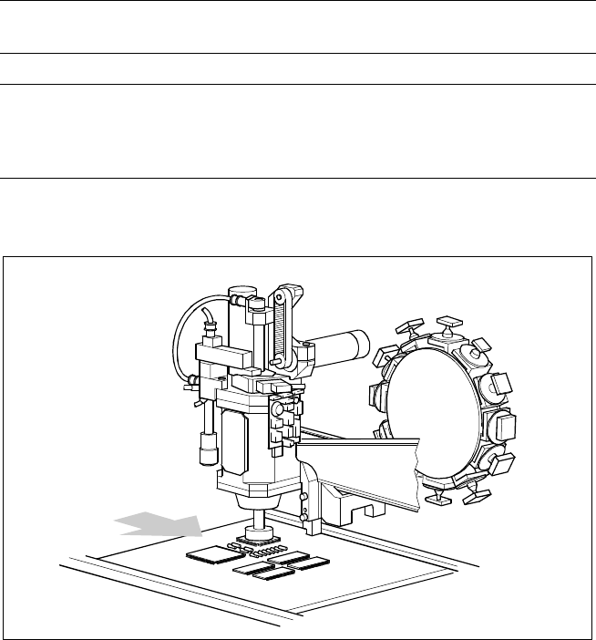
Description
The main X-/Y-gantry features two
placement heads, the 12-nozzle
high-speed revolver placement
head and the high-precision Pick &
Place head or Fine Pitch place-
ment head.
With certain overlapping, each
placement head is specialized for a
specific range of components.
Therefore it is possible to option-
ally distribute the components to
be placed between the two heads.
Placement Heads
Technical Data
Placement principle
Pick & Place (Pick & Place head)
Collect & Place (Revolver head)
Components Entire SMD range
Component table:
Pick & Place head
12-nozzle revolver head
Feeder on changeover table
Waffle Pack Changer or manual trays
Feeder on changeover table
Placement Heads SIPLACE 80 F
4
Pick & Place Head
Collect & Place
Revolver Head
PCB Transport
Direction
6
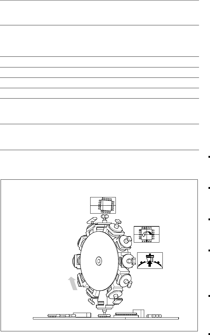
Revolver Head Function
Component Pick-Up/
Placement
Segment
Removal
Point
Turning to
the Placement
Position
Component
Vision
Description
The 12-nozzle revolver head oper-
ates on the Collect & Place princi-
ple. In contrast to classic shooters
the 12 vacuum nozzles of the
SIPLACE revolver heads rotate
around a horizontal axis. Due to
the small diameter the centrifugal
forces which develop are much
lower than with chipshooters. The
results are reliable placement and
the same cycle time for all compo-
nents.
The components are picked up
and placed gently and reliably with
the aid of vacuum or blast air. A
number of vacuum tests indicate
whether the component was
picked up and set down correctly.
Different control and self-learning
functions further enhance the reli-
ability of the system:
The optical position recognition
unit for the feeder ascertains
the exact position of the com-
ponent table.
A camera on the revolver head
(component vision module) de-
termines the exact position of
each component on the nozzle.
Offsets are corrected prior to
placement and taken into ac-
count during the subsequent
component pick-up process.
In addition, the geometric form
(package form) is also checked.
If the actual geometric dimen-
sions of the component do not
correspond to those pro-
grammed, it is not placed.
Irregular PCB surfaces are eve-
ned out by the sensor stop ope-
ration while the nozzle is being
lowered and they are also
“learned”.
Components recognized as
faulty are ejected by blast air
and automatically repaired in a
repair cycle.
Placement Heads:
12-Nozzle Revolver Head for High-Speed
Technical Data
Component spectrum*
0402 to 18.7 x 18.7 mm,
incl. BGA, µBGA, Flip Chip, QFP,
TSOP, PLCC, SO to SO32, DRAM
Height*
min. lead pitch
min. dimensions
max. dimensions
6 mm
0.5 mm
0.5 x 1.0 mm
18.7 x 18.7 mm
Weight* 2 g
Stroke of Z-axis max. 16 mm
Programmable placement force 2.4 to 5.0 N
Benchmark placement rate 10,000 cph
Angle accuracy
± 0.525° / 3 σ
± 0.70° / 4 σ
± 1.05° / 6 σ
Placement accuracy
± 67.5 µm/ 3 σ
± 90 µm/ 4 σ
± 135 µm/ 6 σ
* Up to these limit values a uniformly reliably, speedy and accurate placement
is
guaranteed over the
entire component range. Furthermore, components can be placed if they satisfy specific basic
conditions (For other components please contact Siemens).