SIPLACE 80 F4_EN.pdf - 第7页
6 Revolver Head Funct ion Component Pick-Up/ Placement Segment Removal Point Turning to the Placement Po s i t i o n Component Vision Description The 12-nozzle revolv er head oper- ates on the Collect & P lace princi…
5
Description
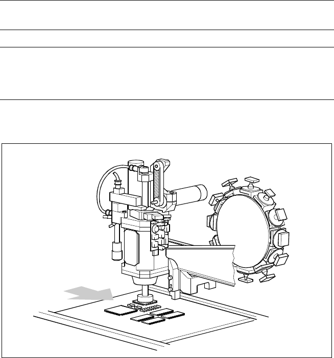
The main X-/Y-gantry features two
placement heads, the 12-nozzle
high-speed revolver placement
head and the high-precision Pick &
Place head or Fine Pitch place-
ment head.
With certain overlapping, each
placement head is specialized for a
specific range of components.
Therefore it is possible to option-
ally distribute the components to
be placed between the two heads.
Placement Heads
Technical Data
Placement principle
Pick & Place (Pick & Place head)
Collect & Place (Revolver head)
Components Entire SMD range
Component table:
Pick & Place head
12-nozzle revolver head
Feeder on changeover table
Waffle Pack Changer or manual trays
Feeder on changeover table
Placement Heads SIPLACE 80 F
4
Pick & Place Head
Collect & Place
Revolver Head
PCB Transport
Direction
6
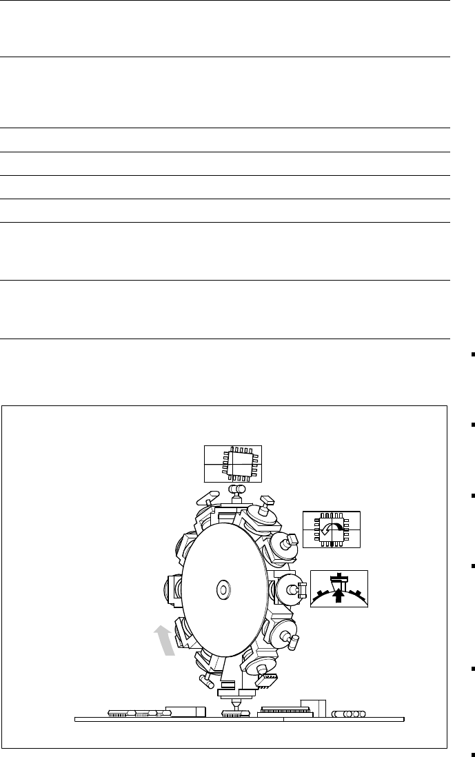
Revolver Head Function
Component Pick-Up/
Placement
Segment
Removal
Point
Turning to
the Placement
Position
Component
Vision
Description
The 12-nozzle revolver head oper-
ates on the Collect & Place princi-
ple. In contrast to classic shooters
the 12 vacuum nozzles of the
SIPLACE revolver heads rotate
around a horizontal axis. Due to
the small diameter the centrifugal
forces which develop are much
lower than with chipshooters. The
results are reliable placement and
the same cycle time for all compo-
nents.
The components are picked up
and placed gently and reliably with
the aid of vacuum or blast air. A
number of vacuum tests indicate
whether the component was
picked up and set down correctly.
Different control and self-learning
functions further enhance the reli-
ability of the system:
The optical position recognition
unit for the feeder ascertains
the exact position of the com-
ponent table.
A camera on the revolver head
(component vision module) de-
termines the exact position of
each component on the nozzle.
Offsets are corrected prior to
placement and taken into ac-
count during the subsequent
component pick-up process.
In addition, the geometric form
(package form) is also checked.
If the actual geometric dimen-
sions of the component do not
correspond to those pro-
grammed, it is not placed.
Irregular PCB surfaces are eve-
ned out by the sensor stop ope-
ration while the nozzle is being
lowered and they are also
“learned”.
Components recognized as
faulty are ejected by blast air
and automatically repaired in a
repair cycle.
Placement Heads:
12-Nozzle Revolver Head for High-Speed
Technical Data
Component spectrum*
0402 to 18.7 x 18.7 mm,
incl. BGA, µBGA, Flip Chip, QFP,
TSOP, PLCC, SO to SO32, DRAM
Height*
min. lead pitch
min. dimensions
max. dimensions
6 mm
0.5 mm
0.5 x 1.0 mm
18.7 x 18.7 mm
Weight* 2 g
Stroke of Z-axis max. 16 mm
Programmable placement force 2.4 to 5.0 N
Benchmark placement rate 10,000 cph
Angle accuracy
± 0.525° / 3 σ
± 0.70° / 4 σ
± 1.05° / 6 σ
Placement accuracy
± 67.5 µm/ 3 σ
± 90 µm/ 4 σ
± 135 µm/ 6 σ
* Up to these limit values a uniformly reliably, speedy and accurate placement
is
guaranteed over the
entire component range. Furthermore, components can be placed if they satisfy specific basic
conditions (For other components please contact Siemens).
7
Description
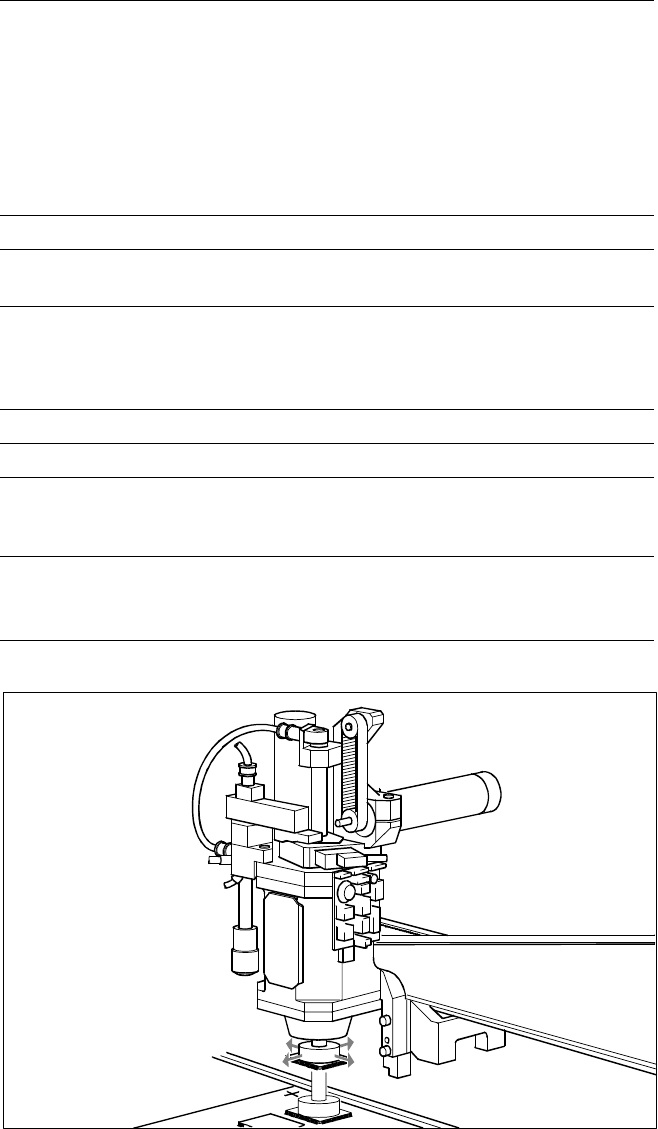
The highly developed Pick & Place
or Fine Pitch placement head op-
erates on the Pick & Place princi-
ple. It is suitable for picking up par-
ticularly sophisticated or large
components as well as non-
standard models. High-resolution,
intelligent vision modules (Fine
Pitch and Flip Chip component vi-
sion modules) ensure that the
components are in satisfactory
condition that the placement posi-
tion is correct.
The sleeve with nozzle is the heart
of the Pick & Place head. The
sleeve is mounted such that it is
movable in the longitudinal (Z-axis)
and rotational direction (D-axis).
Each of the two axis are driven by
a DC motor; positioning is done by
incremental encoder. Thanks to a
high-resolution glass incremental
panel on the sleeve, the Pick &
Place head has an outstanding
high rotational position accuracy.
The rotating movement is trans-
mitted directly from D-axis motor
to the driving plate on the sleeve
via frictional wheel.
Placement Heads:
Pick & Place Head for High End / High Accuracy IC Placement
Technical Data
Component range
max. height
min. lead pitch
max. dimensions
max. weight
PCB-height ≤ 13.5 mm (20 mm* opti-
on) – thickness (PCB) – arching (PCB)
0.4 mm (standard), 0.25 mm (option)
32 x 32 mm (single measurement)
55 x 55 mm (multiple measurement)
25 g
Programmable placement force 1 to 10 N
Nozzles types
5 standard nozzles including
Flip Chip nozzle with nozzle changer
Component centering
Fine Pitch component vision module
(standard)
Flip Chip component vision module
(option)
Benchmark placement rate 1,800 cph
Resolution of the D-axis 0.005°
Angle accuracy
± 0.052° / 3 σ
± 0.07° / 4 σ
± 0.105° / 6 σ
Placement accuracy
± 37.5 µm/ 3 σ
± 50 µm/ 4 σ
± 75 µm/ 6 σ
* max. PCB-height is depending on the feeder (please contact Siemens service)
Pick & Place Head
PCB Transport
Direction