EdisonStandardOwnersManual-RevA-20170818B.pdf - 第43页
Edison Printer User Manual (Part Number 1023838) S AFETY Rev. A 43 Copyright © 2017 ITW EAE All rights reserved. No part of the contents of this manual may be reproduced, copi ed or transmi tted in any form or by any mea…
SAFETY Edison Printer User Manual (Part Number 1023838)
42 Rev. A
Copyright © 2017 ITW EAE
All rights reserved. No part of the contents of this manual may be reproduced, copied or transmitted in any form or by any
means including graphic, electronic, or mechanical methods or photocopying, recording, or information storage and
retrieval systems without the written permission of ITW EAE, unless for purchaser's personal use.
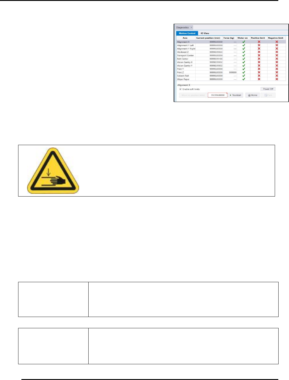
2.8.3. Motion Control
Motion Control allows movement of the printer
components along the different axes during set-up and
preventive maintenance routines.
Printer motion is available via the Motion Control
screen (Figure 16).
Access the Motion Control access this screen:
1. Select View > Diagnostics from the menu bar at
the top of the screen.
2. Click the Motion Control Quick Link.
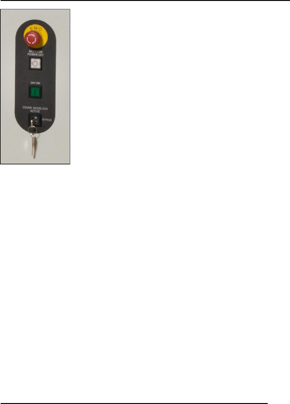
2.8.4. Interlock Bypass and Printer Motion
Service and maintenance procedures (for instance, calibration) require access to the printer
interior while motion is active. Use the Interlock Bypass key switch to open the hood and jog
axes while the printer is in motion. During these situations, speed is reduced to twenty-five
percent (25%) for all axes. Axes will travel at normal speed with the key set to Bypass and the
hood closed.
Use the Interlock Bypass key only when instructed by the Intueri
software.
Ensure the printer is free of objects that may interfere with or
obstruct movement before you initialize or jog any printer
component. Failure to comply may result in printer damage.
Caution!
Keep hands clear of printer while testing printer motion.
Figure 16. Motion Control Screen.
Edison Printer User Manual (Part Number 1023838) SAFETY
Rev. A 43
Copyright © 2017 ITW EAE
All rights reserved. No part of the contents of this manual may be reproduced, copied or transmitted in any form or by any
means including graphic, electronic, or mechanical methods or photocopying, recording, or information storage and
retrieval systems without the written permission of ITW EAE, unless for purchaser's personal use.
Place the key in the horizontal position to open the hood and jog axes
(Figure 17). Close the hood and set the key in the vertical position to
return the printer to normal operating speed.
Figure 17. Key position:
vertical vs. horizontal.
INSTALLATION AND INITIAL START-UP Edison Printer User Manual (Part Number 1023838)
44 Rev. A
Copyright © 2017 ITW EAE
All rights reserved. No part of the contents of this manual may be reproduced, copied or transmitted in any form or by any
means including graphic, electronic, or mechanical methods or photocopying, recording, or information storage and
retrieval systems without the written permission of ITW EAE, unless for purchaser's personal use.
3. Installation, Initial Start-Up and Decommissioning
This section provides information required for unpacking, set up, positioning, connecting,
powering up, initialization and decommissioning. This information applies to the Edison printer
Models 100, 200, and 300.
3.1. Site Requirements
Before unpacking the Edison printer, review the physical dimensions (Section 1.7.1) and floor
space requirements (Section 1.7.2) to ensure requirements are met. Refer to Table 1 for printer
dimensions
Attention
Printer weights may vary according to printer model. Refer to
the facility layout drawings for full printer dimensions.
3.1.1. Facility Environment
Install the Edison in a clean, dust-free environment to ensure proper operation.
3.1.2. Service Clearance
Ensure a clearance of 24 in (610 mm) around the printer to provide adequate space for service.
3.1.3. Facility Requirements
Table 14 lists Edison printer facility requirements.
Table 14. Facility Requirements.
Electrical Power
200-240VAC (+ 10%) @ 50/60 Hz, 20A
Air Supply Requires
clean, dry air
90 psi @ 4 cfm (standard run mode) to 18 cfm (vacuum wipe)
(6.20 bar @ 1.9L/s to 8.5L/s), 12.7 mm (0.5”) diameter line
Minimum Front Clearance
20 in (508 mm)
Minimum Rear Clearance
20 in (508 mm)