EdisonStandardOwnersManual-RevA-20170818B.pdf - 第54页
I NSTALLATION AND I NITIA L S T A R T -U P Edison Printer User Manual (Part Number 1023838) 54 Rev. A Copyright © 2017 ITW EAE All rights reserved. No part of the contents of thi s manual may be reproduced, copied or tra…
Edison Printer User Manual (Part Number 1023838) INSTALLATION AND INITIAL START-UP
Rev. A 53
Copyright © 2017 ITW EAE
All rights reserved. No part of the contents of this manual may be reproduced, copied or transmitted in any form or by any
means including graphic, electronic, or mechanical methods or photocopying, recording, or information storage and
retrieval systems without the written permission of ITW EAE, unless for purchaser's personal use.
3.3.4. Power, Air and Interface Connections
Connect power, air and line interfaces after the printer is properly positioned in the intended area
of operation
3.3.4.1. Electrical Connections
1. Ensure the Main Circuit Breaker/Disconnect switch is set to OFF (Figure 12).
2. Measure the facility power source and verify it meets printer power specifications (Table 14).
3. Connect the supplied power cable (located at the rear of the printer) to the facility power
source.
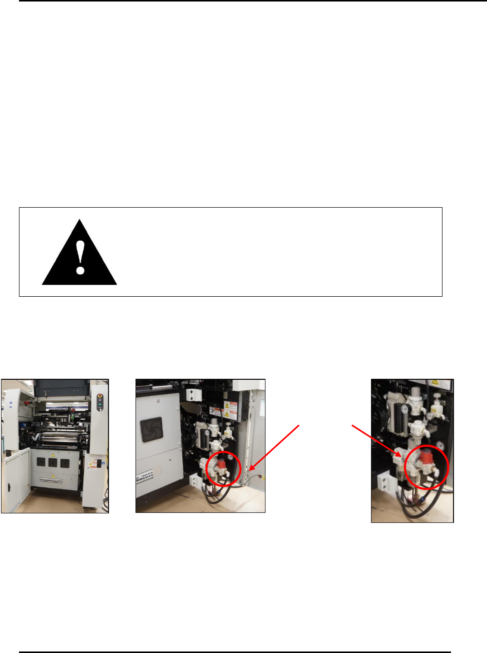
3.3.4.2. Pneumatic Connections
Attention
The standard connection accommodates ½ in. OD tubing.
The shipping kit contains a fitting to adapt this connection to
a factory metric air connection.
1. Before connecting the air supply, purge the air supply to remove all contaminants (for
instance, condensation or dirt).
2. Open the middle front door of the printer (Figure 27).
3. Open the right front door to access the pneumatics panel.
4. Connect the facility air line to the printer connection (Figure 27).
Connect
facility air line
to printer
Figure 27. Connecting facility air.
INSTALLATION AND INITIAL START-UP Edison Printer User Manual (Part Number 1023838)
54 Rev. A
Copyright © 2017 ITW EAE
All rights reserved. No part of the contents of this manual may be reproduced, copied or transmitted in any form or by any
means including graphic, electronic, or mechanical methods or photocopying, recording, or information storage and
retrieval systems without the written permission of ITW EAE, unless for purchaser's personal use.
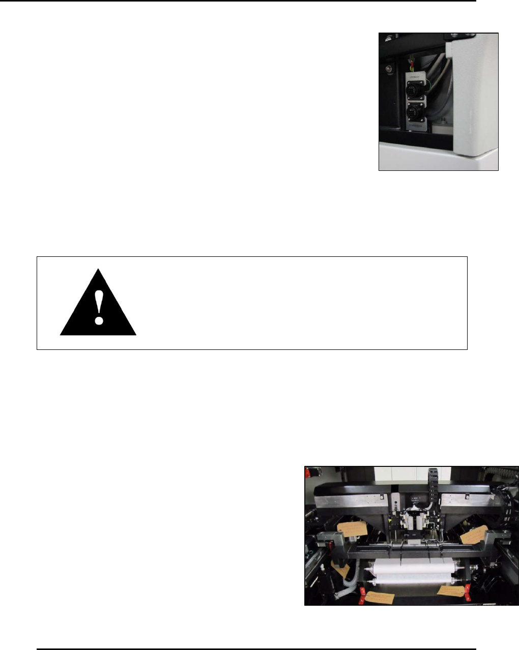
3.3.4.3. Interface Cable Installation
Follow this procedure to install printer SMEMA (Surface Mount
Equipment Manufacturers Association) interface cables. Review the
Interface Schematic (1021368) for the interface of preceding (Upstream)
and succeeding (Downstream) machines.
1. Set printer power to OFF.
2. Remove the two interface cables (Qty. 2 of P/N: CA-1004) from the shipping kit
supplied with the printer.
3. Plug the cables (Upstream and Downstream) into the SMEMA
connectors located inside the hood just above the pneumatics door.
4. Route both cables out through the bottom of the printer and to their
destination machines.
Attention
Before the installation is considered complete and the printer
fully operation, an ITW EAE representative must calibrate the
printer and complete the installation checklist.
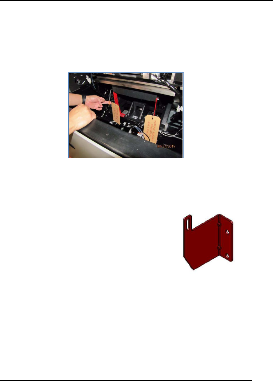
3.4. Remove Transit Material
Edison printer assemblies may be secured with cable ties, packing material, and shipping brackets
to protect them during transit. Remove these materials and associated Remove Before Operation
(RBO) tags prior to printer operation (Figure 29).
Figure 28. Upstream and
Downstream SMEMA
connectors
Figure 29. Remove Before Operation Tags.
Edison Printer User Manual (Part Number 1023838) INSTALLATION AND INITIAL START-UP
Rev. A 55
Copyright © 2017 ITW EAE
All rights reserved. No part of the contents of this manual may be reproduced, copied or transmitted in any form or by any
means including graphic, electronic, or mechanical methods or photocopying, recording, or information storage and
retrieval systems without the written permission of ITW EAE, unless for purchaser's personal use.
3.4.1. Hood Blocks
Remove the two foam blocks from between the hood and the side covers.
3.4.2. Table Lift Brackets
Remove the two table lift shipping brackets and the RBO tags at the rear of the rear table
assembly (Figure 30).
3.4.3. Vision XY Bracket
Remove the one Vision XY shipping bracket and associated RBO securing the vision gantry to
the right side of the printer frame, as viewed from the rear of the
printer.
Figure 30. Remove Table Lift Brackets.
Figure 31. Remove Vision
XY Bracket.