EdisonStandardOwnersManual-RevA-20170818B.pdf - 第57页
Edison Printer User Manual (Part Number 1023838) I NSTALLATION AND I NITIA L S T A RT - U P Rev. A 57 Copyright © 2017 ITW EAE All rights reserved. No part of the contents of this manual may be reproduced, copi ed or tra…
INSTALLATION AND INITIAL START-UP Edison Printer User Manual (Part Number 1023838)
56 Rev. A
Copyright © 2017 ITW EAE
All rights reserved. No part of the contents of this manual may be reproduced, copied or transmitted in any form or by any
means including graphic, electronic, or mechanical methods or photocopying, recording, or information storage and
retrieval systems without the written permission of ITW EAE, unless for purchaser's personal use.
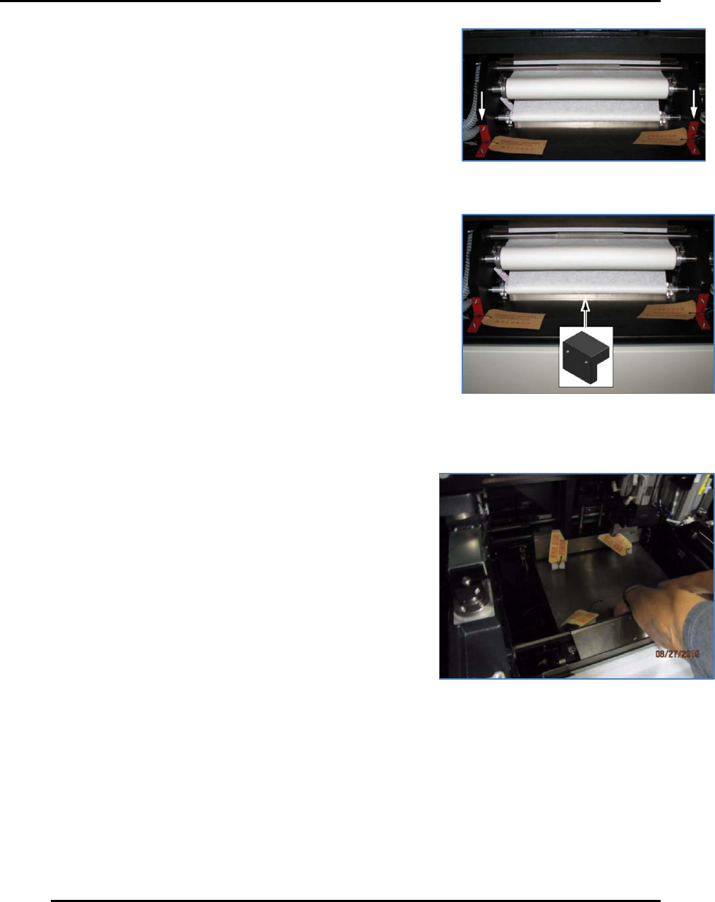
3.4.4. Wiper Bracket (Front)
Remove the two front wiper shipping brackets and RBO tags
securing the wiper to the frame (Figure 32).
3.4.5. Wiper Bracket (Rear)
Remove the rear wiper shipping bracket and RBO tag, located
behind the take-up roll (Figure 33).
3.4.6. Panel Support Blocks (Front and Rear)
Lift the front panel support and remove the two foam
blocks from between the panel support and the work table.
Repeat for the rear panel support (Figure 34).
Figure 32. Remove two front wiper
shipping brackets.
Figure 33. Remove rear wiper shipping
bracket.
Figure 34. Remove panel support blocks--front
& rear.
Edison Printer User Manual (Part Number 1023838) INSTALLATION AND INITIAL START-UP
Rev. A 57
Copyright © 2017 ITW EAE
All rights reserved. No part of the contents of this manual may be reproduced, copied or transmitted in any form or by any
means including graphic, electronic, or mechanical methods or photocopying, recording, or information storage and
retrieval systems without the written permission of ITW EAE, unless for purchaser's personal use.
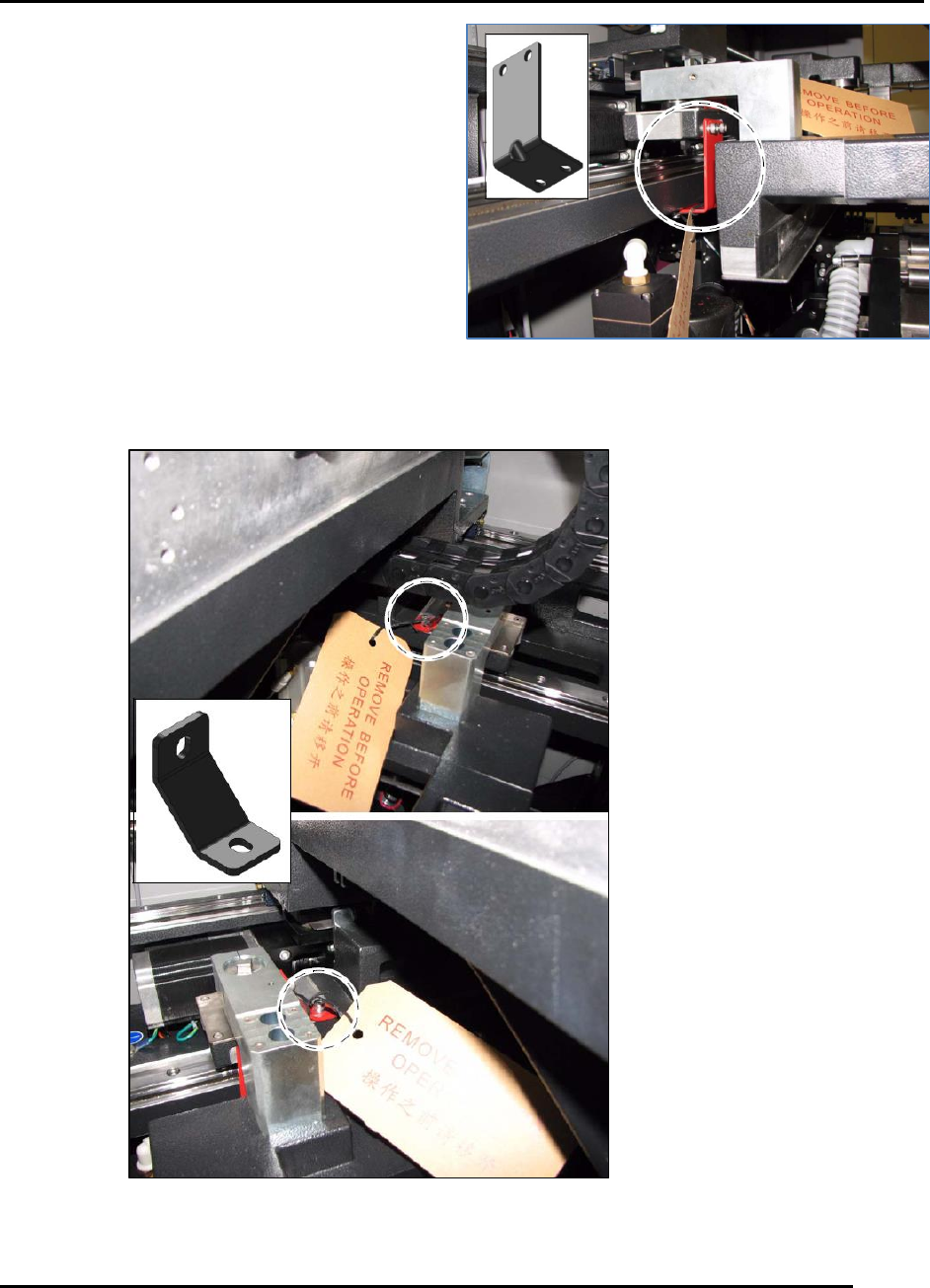
3.4.7. Shuttle Brackets
Remove the two shuttle shipping brackets and
associated RBO tags from the printer (Figure 35).
3.4.8. Stage Brackets
Remove the two stage shipping brackets and
associated RBO tags from the right and left sides of
the printer (Figure 36).
Figure 35. Remove two shuttle brackets.
Figure 36. Remove two stage brackets.
INSTALLATION AND INITIAL START-UP Edison Printer User Manual (Part Number 1023838)
58 Rev. A
Copyright © 2017 ITW EAE
All rights reserved. No part of the contents of this manual may be reproduced, copied or transmitted in any form or by any
means including graphic, electronic, or mechanical methods or photocopying, recording, or information storage and
retrieval systems without the written permission of ITW EAE, unless for purchaser's personal use.
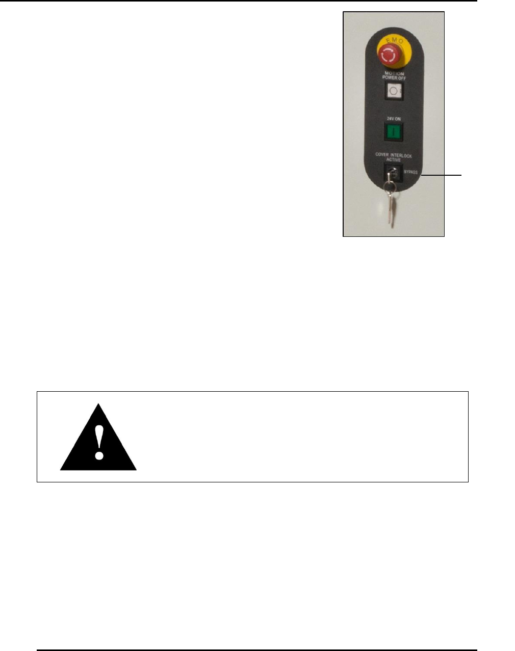
Cover
Interlock
Key
3.4.9. Cover Interlock Key
Remove the cover interlock key and associated RBO tag from the
front right of the printer (Figure 37).
3.5. Initial Power Up
3.5.1. Emergency Stop and Main Disconnect Switches
Locate the Emergency Stop (Figure 15) and Main Disconnect (Figure 12) switches on the front of
the Edison printer.
Attention
After having been pushed, the Emergency Stop button
requires a twist to release.
Figure 37. Remove
Cover Interlock Key.