EdisonStandardOwnersManual-RevA-20170818B.pdf - 第58页
I NSTALLATION AND I NITIA L S T A R T -U P Edison Printer User Manual (Part Number 1023838) 58 Rev. A Copyright © 2017 ITW EAE All rights reserved. No part of the contents of thi s manual may be reproduced, copied or tra…
Edison Printer User Manual (Part Number 1023838) INSTALLATION AND INITIAL START-UP
Rev. A 57
Copyright © 2017 ITW EAE
All rights reserved. No part of the contents of this manual may be reproduced, copied or transmitted in any form or by any
means including graphic, electronic, or mechanical methods or photocopying, recording, or information storage and
retrieval systems without the written permission of ITW EAE, unless for purchaser's personal use.
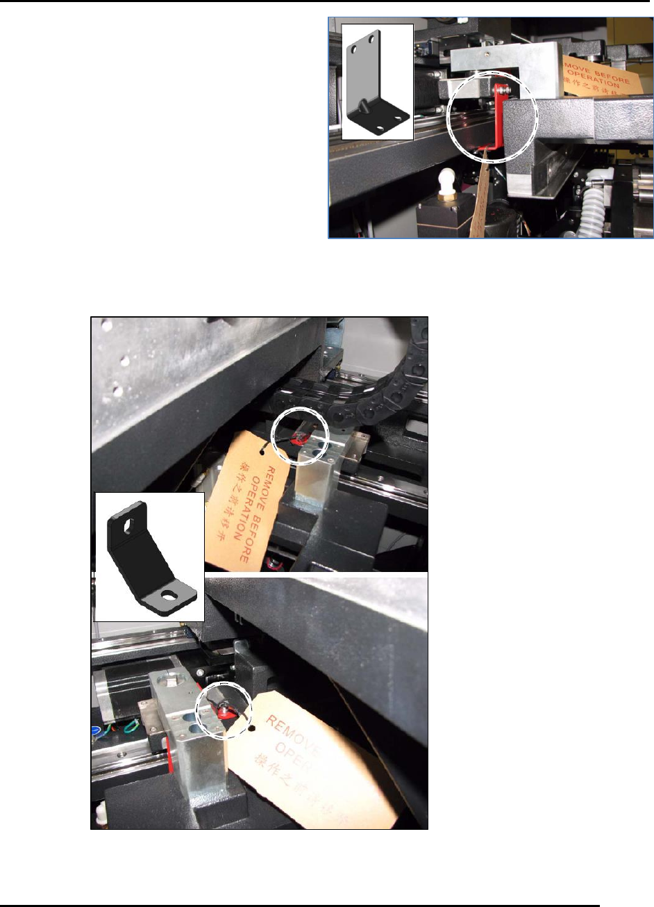
3.4.7. Shuttle Brackets
Remove the two shuttle shipping brackets and
associated RBO tags from the printer (Figure 35).
3.4.8. Stage Brackets
Remove the two stage shipping brackets and
associated RBO tags from the right and left sides of
the printer (Figure 36).
Figure 35. Remove two shuttle brackets.
Figure 36. Remove two stage brackets.
INSTALLATION AND INITIAL START-UP Edison Printer User Manual (Part Number 1023838)
58 Rev. A
Copyright © 2017 ITW EAE
All rights reserved. No part of the contents of this manual may be reproduced, copied or transmitted in any form or by any
means including graphic, electronic, or mechanical methods or photocopying, recording, or information storage and
retrieval systems without the written permission of ITW EAE, unless for purchaser's personal use.
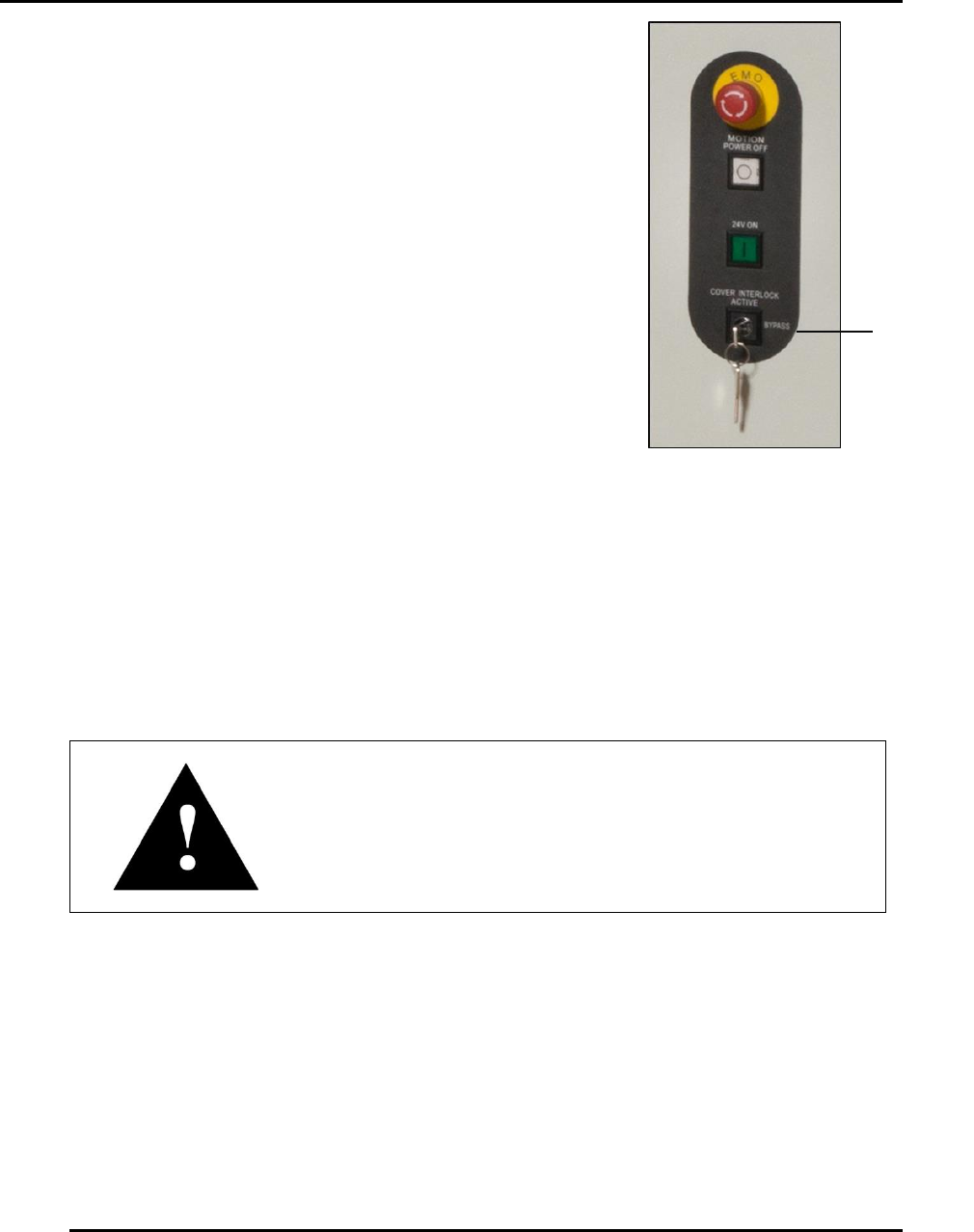
Cover
Interlock
Key
3.4.9. Cover Interlock Key
Remove the cover interlock key and associated RBO tag from the
front right of the printer (Figure 37).
3.5. Initial Power Up
3.5.1. Emergency Stop and Main Disconnect Switches
Locate the Emergency Stop (Figure 15) and Main Disconnect (Figure 12) switches on the front of
the Edison printer.
Attention
After having been pushed, the Emergency Stop button
requires a twist to release.
Figure 37. Remove
Cover Interlock Key.
Edison Printer User Manual (Part Number 1023838) INSTALLATION AND INITIAL START-UP
Rev. A 59
Copyright © 2017 ITW EAE
All rights reserved. No part of the contents of this manual may be reproduced, copied or transmitted in any form or by any
means including graphic, electronic, or mechanical methods or photocopying, recording, or information storage and
retrieval systems without the written permission of ITW EAE, unless for purchaser's personal use.
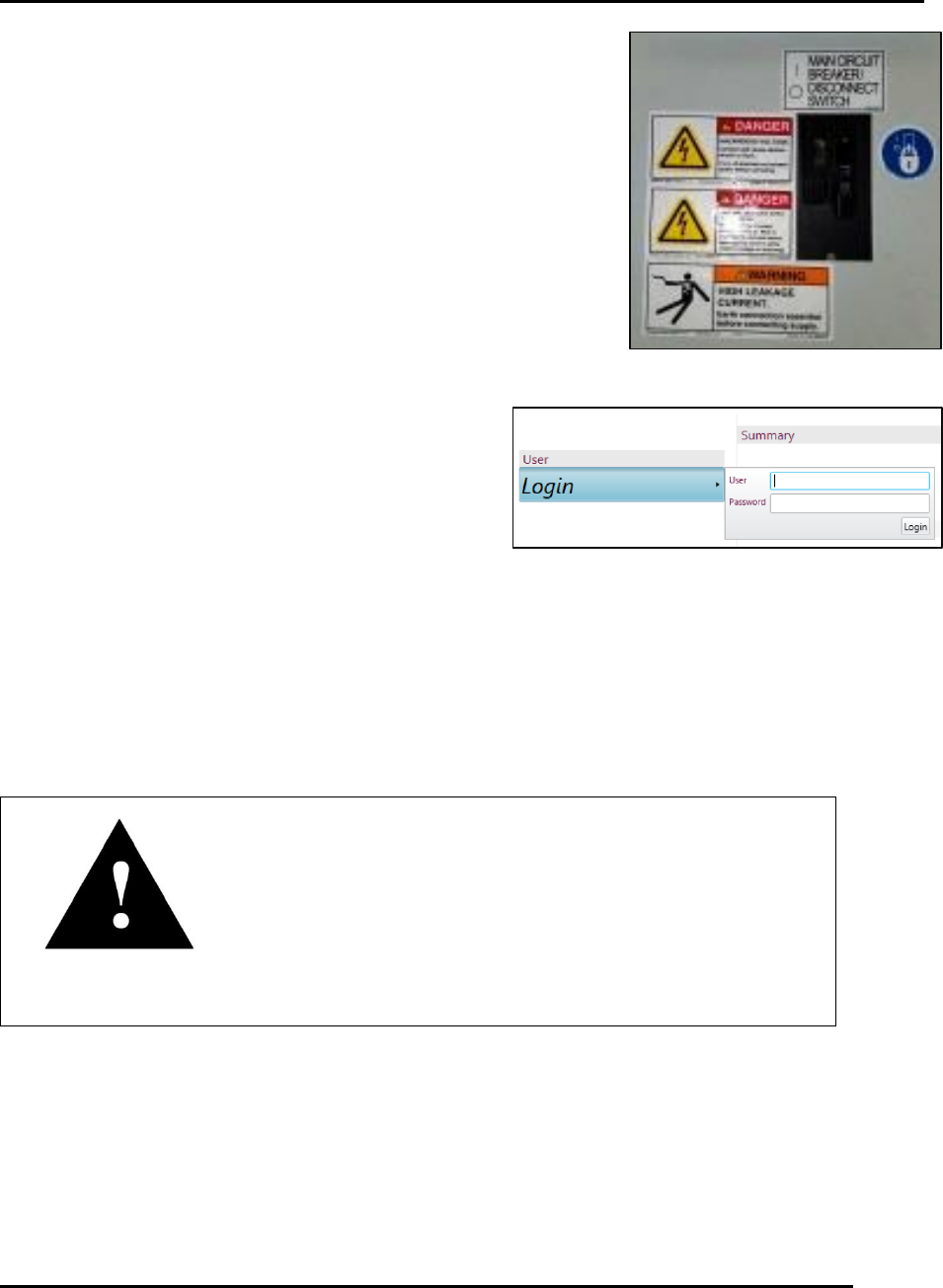
3.5.2. Power Up and Initialization
1. Set the Main Disconnect switch to ON ().
2. Press the green Control Power ON button.
a. If the green light comes on but does not stay on, check the
Emergency Stop button and/or the circuit breakers on the
Power Control Module located inside the front door.
b. If the computer does not automatically come on, again press
the green Control Power ON.
3. Log on to Windows.
a. The factory default password is MerlinAdmin.
4. Start the Intueri software.
5. Log on using the Login screen (Figure 39).
a. The default User is Administrator and the default Password is Admin.
b. Click Initialize on the following screen.
6. If programs do not exist, select the Load button to
close the load prompt, then select File>New>Process Program to begin teaching a new
program.
7. If programs do exist, highlight the desired process program and then select Load or simply
double click the program name.
Attention
When loading a previously created process, the Changeover
process begins automatically. To load the process program
without completing the Changeover process, click Cancel at
the bottom of the page.
3.6. Front and Rear Foil Installation
The four foils to be installed are located in the shipping kit. Additional foil mounting hardware
has also been provided in the shipping kit in the event hardware gets lost during foil installation.
Two sets of replacement hardware have been provided: one with flat head slotted screws (Qty. 50
of P/N P11085) and the other with flat head Phillips screws (Qty. 50 of P/N: P11084). Flat head
Phillips screws are currently installed in the machine.
Figure 39. Log on using the Intueri Login screen.
Figure 38. Main Disconnect.