EdisonStandardOwnersManual-RevA-20170818B.pdf - 第71页
Edison Printer User Manual (Part Number 1023838) P ROCESS P ROGRA M C REATION Rev. A 71 Copyright © 2017 ITW EAE All rights reserved. No part of the contents of this manual may be reproduced, copi ed or transmi tted in a…
PROCESS PROGRAM CREATION Edison Printer User Manual
70 Rev. A
Copyright © 2017 ITW EAE
All rights reserved. No part of the contents of this manual may be reproduced, copied or transmitted in any form or by any
means including graphic, electronic, or mechanical methods or photocopying, recording, or information storage and
retrieval systems without the written permission of ITW EAE, unless for purchaser's personal use.
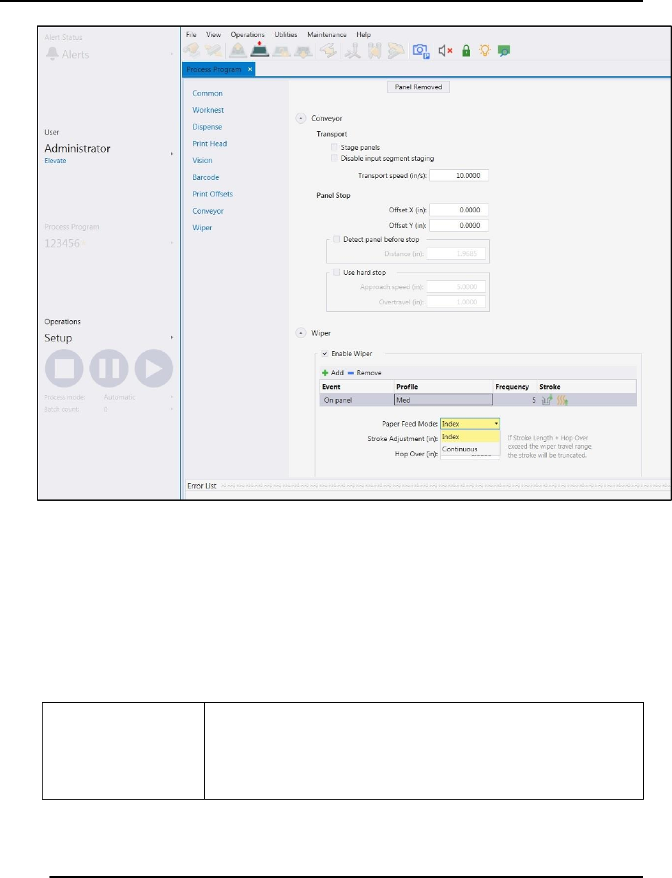
In the Identification section, manually enter text describing:
Tooling ID
Squeegee ID
Stencil ID
Pump ID
Pump Size
Material
Do not use Identification fields for barcodes.
Barcodes are entered later using the Teach Board Barcode
Wizard.
In the Panel section, manually enter:
Figure 44. Process Program Page--Common Section.
Edison Printer User Manual (Part Number 1023838) PROCESS PROGRAM CREATION
Rev. A 71
Copyright © 2017 ITW EAE
All rights reserved. No part of the contents of this manual may be reproduced, copied or transmitted in any form or by any
means including graphic, electronic, or mechanical methods or photocopying, recording, or information storage and
retrieval systems without the written permission of ITW EAE, unless for purchaser's personal use.
Panel Size X
Panel Size Y
Thickness of the panel to be printed
In the Stencil section, manually enter:
Stencil X dimensions
Stencil Y dimensions
Inner Dimension of the stencil
Stencil image offsets
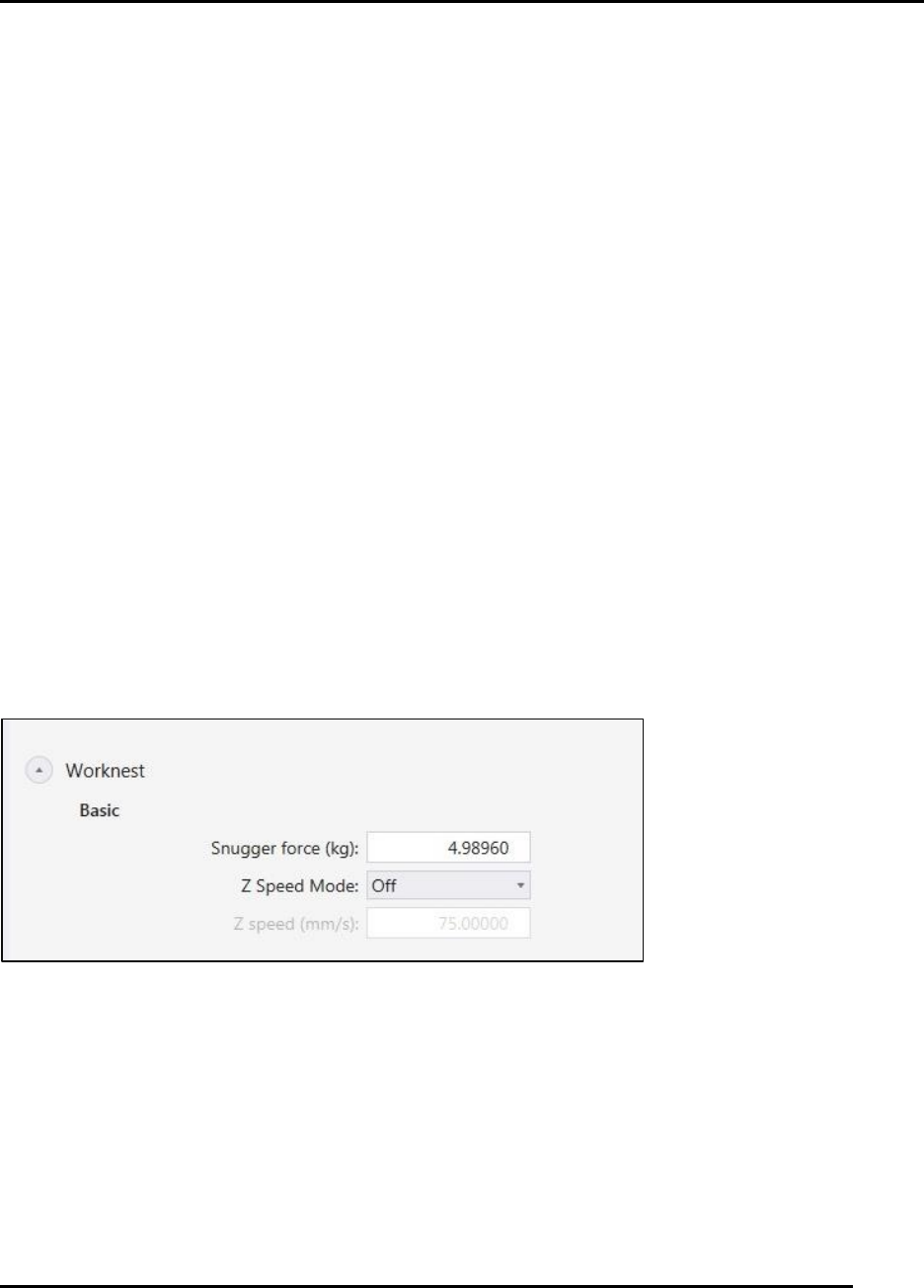
4.2.2. Worknest Program Data
Worknest program data establishes the force and movement specifics for controlling the
worknest. Enter specifics required to operate the worknest (Figure 45)
In the Basic section, choose between:
Snugger Force (Range varies from 0 to 22 Lbs. or 0 to 10 Kg.)
Z Speed mode. Choose between
o Off
o Snug
o Release
o Snug and Release
o Full Print cycle
Z speed (Range varies from 0.00492 to 10 inch / sec or 0.125 to 254.0 mm / sec)
Figure 45. Process Program Page--Worknest Section.
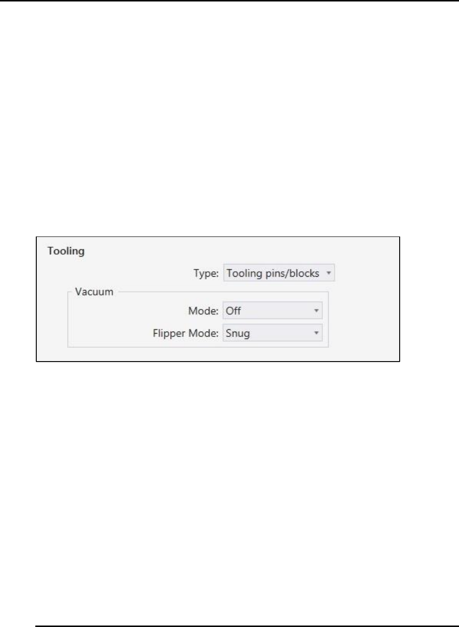
4.2.3. Tooling Program Data
Tooling program data sets up the tooling pin layout diagram to use as reference when manually
placing pins for board support on the worknest. Enter specifics required to operate the tooling
(Figure 48)
In the Types of Tooling section choose between:
No tooling
PROCESS PROGRAM CREATION Edison Printer User Manual
72 Rev. A
Copyright © 2017 ITW EAE
All rights reserved. No part of the contents of this manual may be reproduced, copied or transmitted in any form or by any
means including graphic, electronic, or mechanical methods or photocopying, recording, or information storage and
retrieval systems without the written permission of ITW EAE, unless for purchaser's personal use.
Dedicated work holder
Tooling Block/pins
Grid Automatic
Grid Manual
In the Vacuum Mode section, choose between:
Off
Snug
Full
On except print
In the Flipper Mode section, choose between:
Off
Snug
Full
Figure 46. Process Program Page--Tooling Section.
4.2.4. Separation Program Data
Separation program data determines the distance between the board and the stencil when the
board is at print height. The separation function also determines how the board separates from the
stencil after the print stroke.
Print Gap: Range available from -0.05 inch to 0.2 inch or -1.27 to 6.35mm.
Separation Profile: Enter the specifics required for separation (Figure 47).