KE-750_QA表.pdf - 第18页
FUNCTION NAME Head Center Distance (Y-Direc tion) Function/Performance CHECK/ADJUSTMENT MET HODS (REMEDIAL ACTION PROCEDURE) ASSURED QUALITY Reliability QUALITY CHARACTERISTI CS (SPECIFICATION VALUES) CATEGORY Safety Pro…
FUNCTION NAME Z-Direction Traveling Parallel Alignment Function/Performance CHECK/ADJUSTMENT METHODS (REMEDIAL ACTION PROCEDURE)
ASSURED QUALITY Reliability
QUALITY CHARACTERISTICS (SPECIFICATION VALUES) CATEGORY Safety
Product Image
ROLE IN FUNCTION (MEANING OF SPECIFICATION VALUES)
POSSIBLE MALFUNCTIONS (CAUSED BY INCORRECT SPECIFICATION VALUES)
COMPONENTS
NO. Part No. Part Name Associated Quality Characteristics
1 E30027250A0 Head unit HD assembly
2 E31027250A0 Head unit LA assembly
3 E32027250A0 Head unit IC assembly MODEL KE-750/760
4 E3019721000 Head center shim A t0.1
UNIT Head
REF. NO.
5 E3020721000 Head center shim B t0.05
NAME
14
6 E3021721000 Head center shim C t0.03
FUNCTION Z-Direction Traveling Parallel
7
NAME Alignment
8
9
10
QA Table
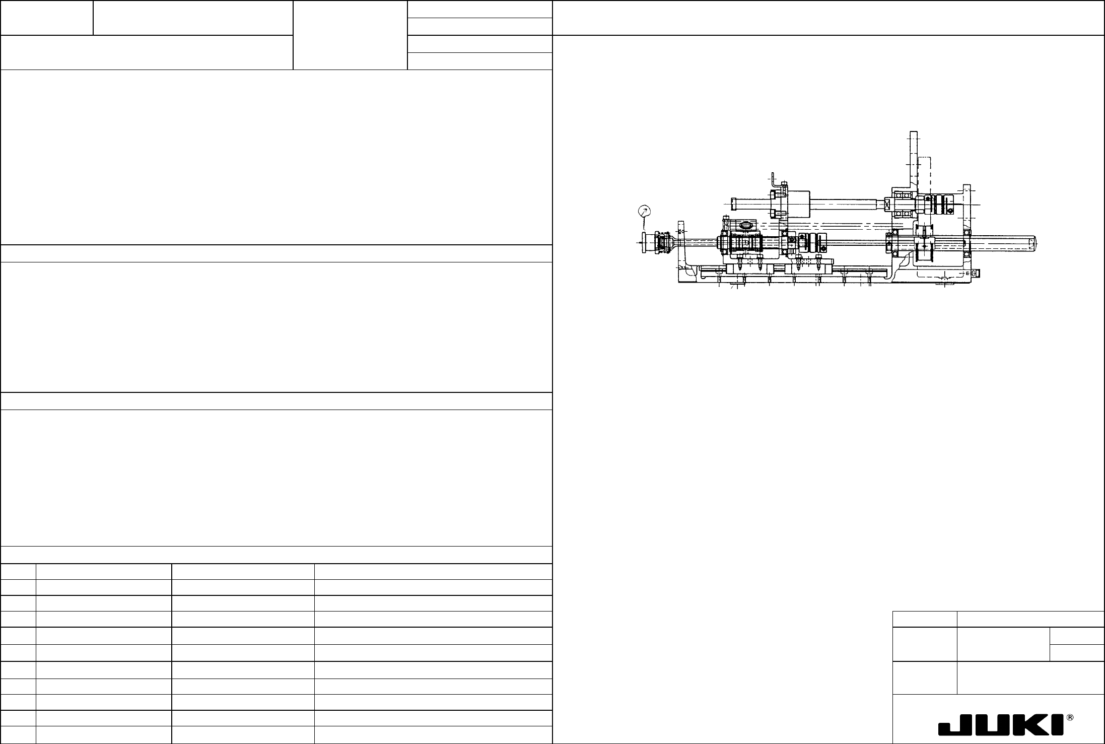
Mount the jig nozzle and measure the eccentric center height at the upper end and lower end of the Z-axis stroke.
Traveling parallel alignment in Z-direction: 0.05 mm or less
Head center shimHead center shim
Jig nozzle
Greatly affects pickup reliability at simultaneous pickup.
Select head center shim A, B, or C as necessary and place it so that the traveling parallel alignment becomes
0.05 mm or less.
– Component pickup failure
– Degraded placement accuracy
FUNCTION NAME Head Center Distance (Y-Direction) Function/Performance CHECK/ADJUSTMENT METHODS (REMEDIAL ACTION PROCEDURE)
ASSURED QUALITY Reliability
QUALITY CHARACTERISTICS (SPECIFICATION VALUES) CATEGORY Safety
Product Image
ROLE IN FUNCTION (MEANING OF SPECIFICATION VALUES)
POSSIBLE MALFUNCTIONS (CAUSED BY INCORRECT SPECIFICATION VALUES)
COMPONENTS
NO. Part No. Part Name Associated Quality Characteristics
1 E30027250A0 Head unit HD assembly
2 E31027250A0 Head unit LA assembly
3 E32027250A0 Head unit IC assembly MODEL KE-750/760
4 E3019721000 Head center shim A t0.1
UNIT Head
REF. NO.
5 E3020721000 Head center shim B t0.05
NAME
15
6 E3021721000 Head center shim C t0.03
FUNCTION Head Center Distance
7 E33037250A0 Head plate assembly (750)
NAME (Y-Direction)
8 E33047250A0 Head plate assembly (760)
9 E33237250A0 Head plate assembly (7520)
10 E33247250A0 Head plate assembly (7620)
QA Table
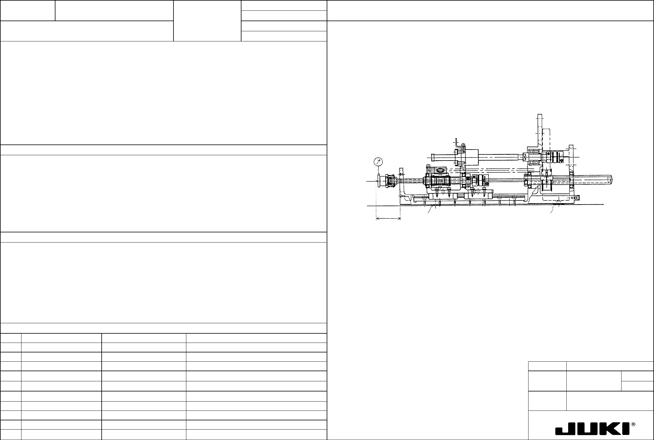
Error in each head in Y-direction with reference to R head: ±0.02 mm (eccentric center as measured at the Z
pickup position)
Mount heads on the head plate and fit the jig nozzle (φ20) to the head that serves as the reference (normally R
head; the head mounted if heads are replaced). With the center of runout in the Y-direction at 0, move the head
in the X-direction. Remove the jig nozzle and, instead, mount it to the head to be measured. Select head
center shim A, B, or C and place it between the head plate and head bracket so that the error in runout center in
Y-direction becomes ±0.02 mm. Measure, at this time, the Z position at the pickup point [see the assembly
drawing of head assembly (750, 760, 7520, 7620)].
Head plate
Head center shimHead center shim
Pickup
height
Greatly affects pickup reliability at simultaneous pickup.
– Component pickup failure
– Degraded placement accuracy
FUNCTION NAME R Head Squareness Function/Performance CHECK/ADJUSTMENT METHODS (REMEDIAL ACTION PROCEDURE)
ASSURED QUALITY Reliability
QUALITY CHARACTERISTICS (SPECIFICATION VALUES) CATEGORY Safety
Product Image
ROLE IN FUNCTION (MEANING OF SPECIFICATION VALUES)
POSSIBLE MALFUNCTIONS (CAUSED BY INCORRECT SPECIFICATION VALUES)
COMPONENTS
NO. Part No. Part Name Associated Quality Characteristics
1 E30027250A0 Head unit HD assembly
2 E32027250A0 Head unit IC assembly
3 E33037250A0 Head plate assembly (750) MODEL KE-750/760
4 E33047250A0 Head plate assembly (760)
UNIT Head
REF. NO.
5 E33237250A0 Head plate assembly (7520)
NAME
16
6 E33247250A0 Head plate assembly (7620)
FUNCTION R Head Squareness
7
NAME
8
9
10
QA Table
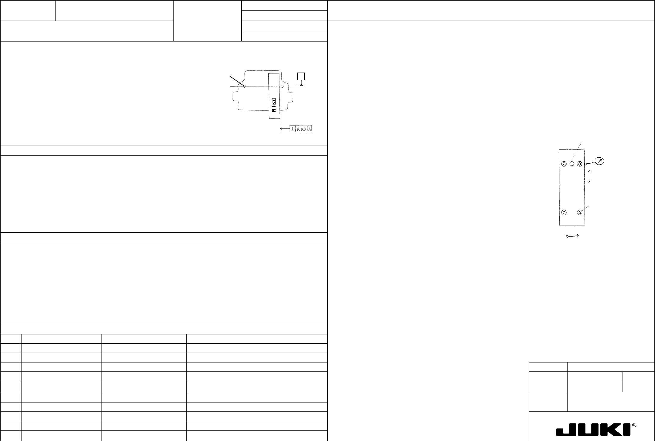
Squareness of the right-hand-side machined surface of the R head with respect to the reference pins (at two
places) of the head plate assembly: 0.03 or less
Check procedure:
Using the square master, measure the machined surface on the right-hand side of the R head with respect
to the reference pins (at two places) of the head plate assembly. If the head plate assembly is connected to
the X-axis frame assembly, measure squareness with the head plate at around the center of the X-axis
frame.
Reference pin
A
Adjustment procedure:
Loosen fixing screws (a) (at four places) of the R head, move the head about positioning pin (b) to meet the
specification value, and then screw the head in position.
Fixing screw (a)
Positioning pin (b)
– Degraded placement accuracy
– Component pickup failure