KE-750_QA表.pdf - 第23页
FUNCTION NAME Z-Axis Home Position Adjust ment Function/Performance CHECK/ADJUSTM ENT MET HODS (REMEDIAL ACTION PROCEDURE) ASSURED QUALITY Reliability QUALITY CHARACTERISTI CS (SPECIFIC ATION VALUES) CATEGORY Safety Prod…
FUNCTION NAME Encoder Centering Function/Performance CHECK/ADJUSTMENT METHODS (REMEDIAL ACTION PROCEDURE)
ASSURED QUALITY Reliability
QUALITY CHARACTERISTICS (SPECIFICATION VALUES) CATEGORY Safety
Product Image
ROLE IN FUNCTION (MEANING OF SPECIFICATION VALUES)
POSSIBLE MALFUNCTIONS (CAUSED BY INCORRECT SPECIFICATION VALUES)
COMPONENTS
NO. Part No. Part Name Associated Quality Characteristics
1 E93057250A0 LAIC θ head encoder assembly
2 E32057250A0 Spline housing IC assembly
3 MODEL KE-750/760
4
UNIT Head
REF. NO.
5
NAME
19
6
FUNCTION Encoder Centering
7
NAME
8
9
10
QA Table
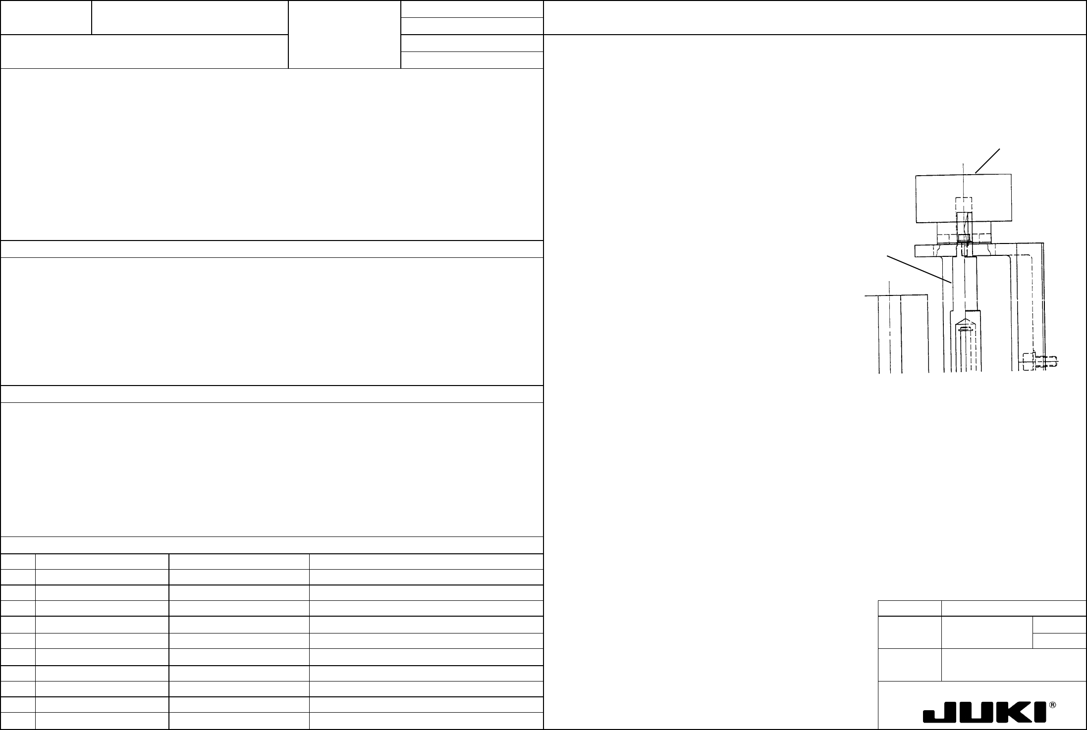
The encoder must be installed in complete alignment with the spline housing IC assembly to prevent an
excessive load from being applied to the flat spring of the encoder. (LAIC only)
Secure the encoder so that rotation of θ-axis (spline housing IC assembly) does not result in load being applied to
the encoder.
Spline housing IC
assembly
Encode
r
Minimizes load applied to the flat spring of the encoder, thereby preventing the flat spring from being damaged.
– Damaged flat spring
FUNCTION NAME Z-Axis Home Position Adjustment Function/Performance CHECK/ADJUSTMENT METHODS (REMEDIAL ACTION PROCEDURE)
ASSURED QUALITY Reliability
QUALITY CHARACTERISTICS (SPECIFICATION VALUES) CATEGORY Safety
Product Image
ROLE IN FUNCTION (MEANING OF SPECIFICATION VALUES)
POSSIBLE MALFUNCTIONS (CAUSED BY INCORRECT SPECIFICATION VALUES)
COMPONENTS
NO. Part No. Part Name Associated Quality Characteristics
1 E30047250A0 Z-slide bracket assembly
2 E93227250A0 Z1 deceleration sensor cable assembly
3 E93237250A0 Z2 deceleration sensor cable assembly MODEL KE-750/760
4 E93247250A0 Z3 deceleration sensor cable assembly
UNIT Head
REF. NO.
5 E3023721000 Coupling
NAME
20
6
FUNCTION Z-Axis Home Position
7
NAME Adjustment
8
9
10
QA Table
Raise the Z-slide bracket up until the Z-sensor is activated. From that point, raise the Z-slide bracket another 1
mm to obtain phase zero of Z-motor. Secure the coupling at this point.
Lock the Z-motor with its phase zero obtained and raise the Z-slide bracket. When the Z-sensor LED lights up,
raise the Z-slide bracket another 1 mm and, at that point, secure the coupling.
Make sure that Z-sensor is activated when the Z-slide bracket is raised to its upper limit.
FUNCTION NAME
θ Belt Tension Function/Performance CHECK/ADJUSTMENT METHODS (REMEDIAL ACTION PROCEDURE)
ASSURED QUALITY Reliability
QUALITY CHARACTERISTICS (SPECIFICATION VALUES) CATEGORY Safety
Product Image
ROLE IN FUNCTION (MEANING OF SPECIFICATION VALUES)
POSSIBLE MALFUNCTIONS (CAUSED BY INCORRECT SPECIFICATION VALUES)
COMPONENTS
NO. Part No. Part Name Associated Quality Characteristics
1 E3023725000 Timing belt θ
2
3 MODEL KE-750/760
4
UNIT Head
REF. NO.
5
NAME
21
6
FUNCTION
θ Belt Tension
7
NAME
8
9
10
QA Table
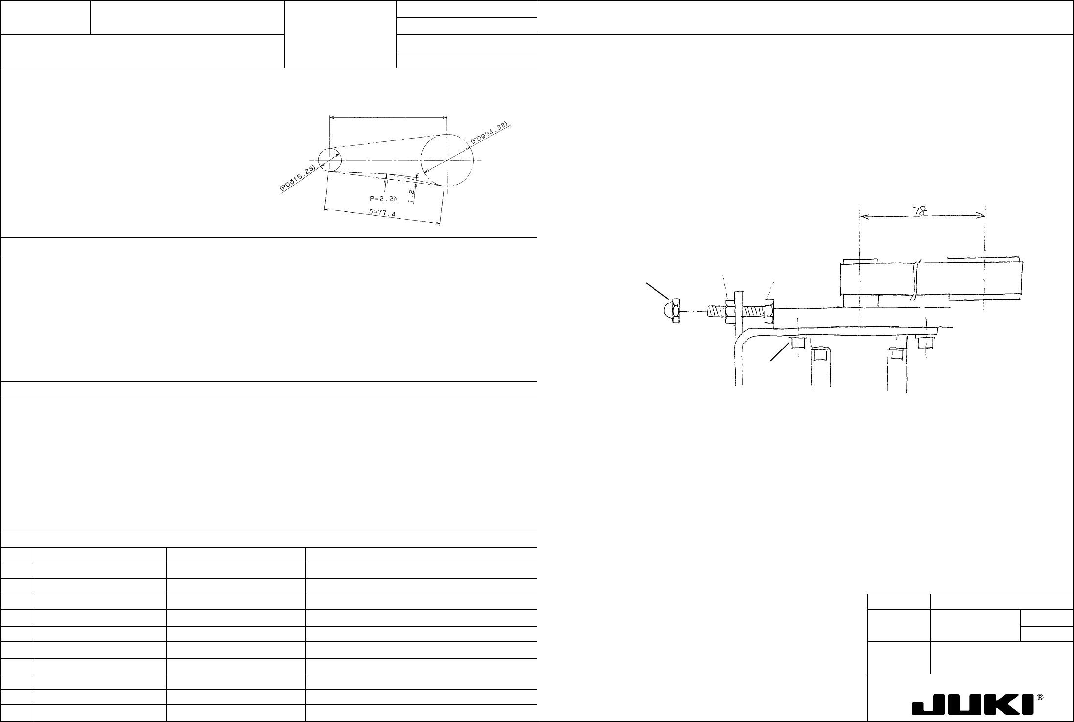
Check procedure:
Tension value: 34.6 N {3.53 kgf} Timing belt θ tension adjustment value
Adjust to obtain a deflection of 1.2 mm when the center of the belt is pushed with a force of 2.2 N {220 gf}
using a spring balance.
Center-to-center distance 78
Adjustment procedure:
Loosen screws (a) at four places and adjust tension in the belt with screw (b). After the adjustment, tighten
nut (c) and bond hexagon cap nut (d) with Loctite 242.
NM6030003SC
Hexagon nut
(c)
SM9031403SC
Hexagon bolt
(Apply Loctite 242.)
NM7030510SA
Hexagon cap nut
(a)
(b)
(d)
SL6030892TN x4 SEMS cap
(tightening torque 1 N.m)
Directly concerned with the θ settling time (damping characteristics), it greatly affects placement accuracy.
Degraded placement accuracy