KE-750_QA表.pdf - 第25页
FUNCTION NAME Diffuser Mounting Position Function/Performance CHECK/ADJUSTMENT MET HODS (REMEDIAL ACTION PROCEDURE) ASSURED QUALITY Reliability QUALITY CHARACTERISTI CS (SPECIFIC ATION VALUES) CATEGORY Safety Product Ima…
FUNCTION NAME
θ Belt Tension Function/Performance CHECK/ADJUSTMENT METHODS (REMEDIAL ACTION PROCEDURE)
ASSURED QUALITY Reliability
QUALITY CHARACTERISTICS (SPECIFICATION VALUES) CATEGORY Safety
Product Image
ROLE IN FUNCTION (MEANING OF SPECIFICATION VALUES)
POSSIBLE MALFUNCTIONS (CAUSED BY INCORRECT SPECIFICATION VALUES)
COMPONENTS
NO. Part No. Part Name Associated Quality Characteristics
1 E3023725000 Timing belt θ
2
3 MODEL KE-750/760
4
UNIT Head
REF. NO.
5
NAME
21
6
FUNCTION
θ Belt Tension
7
NAME
8
9
10
QA Table
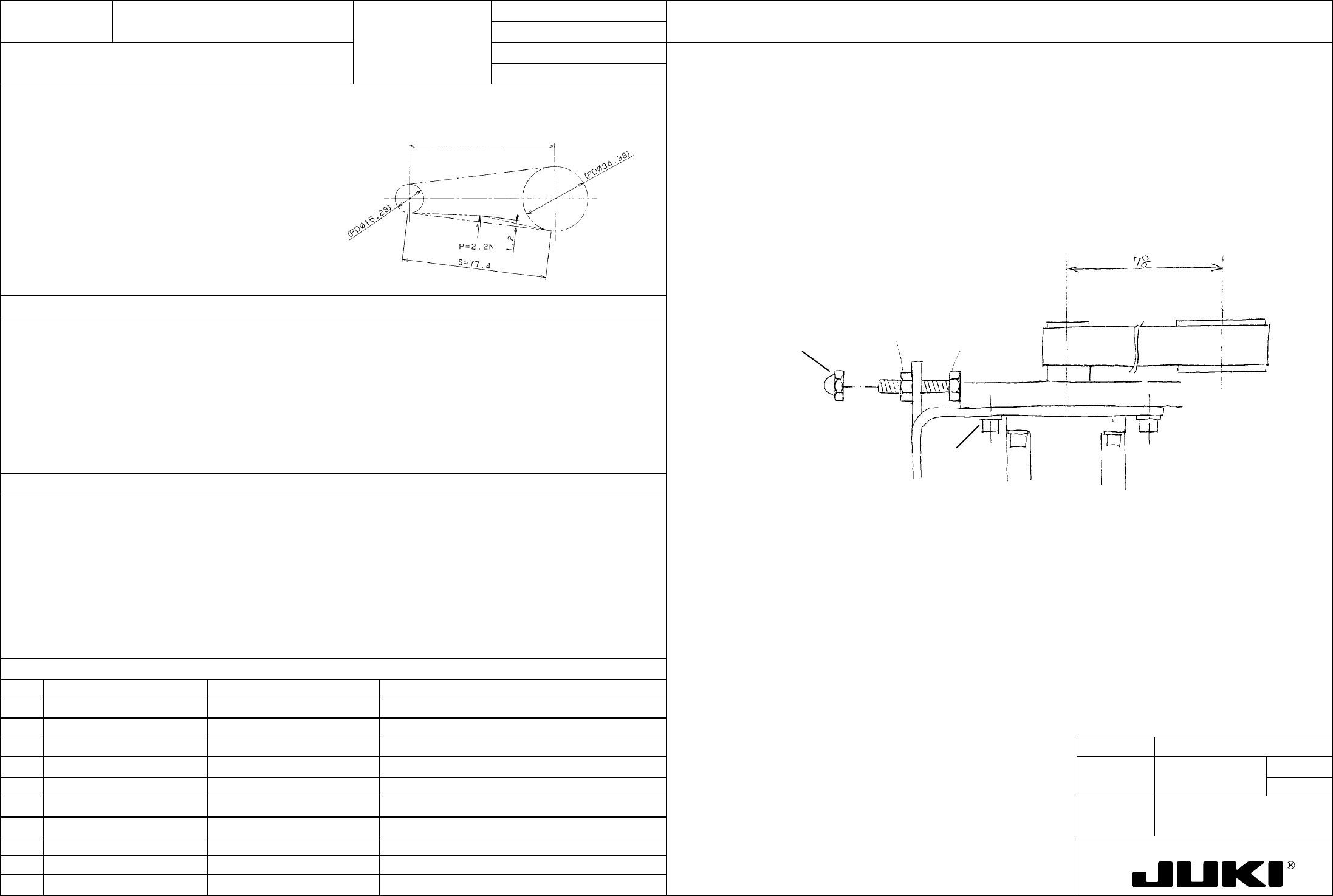
Check procedure:
Tension value: 34.6 N {3.53 kgf} Timing belt θ tension adjustment value
Adjust to obtain a deflection of 1.2 mm when the center of the belt is pushed with a force of 2.2 N {220 gf}
using a spring balance.
Center-to-center distance 78
Adjustment procedure:
Loosen screws (a) at four places and adjust tension in the belt with screw (b). After the adjustment, tighten
nut (c) and bond hexagon cap nut (d) with Loctite 242.
NM6030003SC
Hexagon nut
(c)
SM9031403SC
Hexagon bolt
(Apply Loctite 242.)
NM7030510SA
Hexagon cap nut
(a)
(b)
(d)
SL6030892TN x4 SEMS cap
(tightening torque 1 N.m)
Directly concerned with the θ settling time (damping characteristics), it greatly affects placement accuracy.
Degraded placement accuracy
FUNCTION NAME Diffuser Mounting Position Function/Performance CHECK/ADJUSTMENT METHODS (REMEDIAL ACTION PROCEDURE)
ASSURED QUALITY Reliability
QUALITY CHARACTERISTICS (SPECIFICATION VALUES) CATEGORY Safety
Product Image
ROLE IN FUNCTION (MEANING OF SPECIFICATION VALUES)
POSSIBLE MALFUNCTIONS (CAUSED BY INCORRECT SPECIFICATION VALUES)
COMPONENTS
NO. Part No. Part Name Associated Quality Characteristics
1
2
3 MODEL KE-750/760
4
UNIT Head
REF. NO.
5
NAME
22
6
FUNCTION Diffuser Mounting Position
7
NAME
8
9
10
QA Table
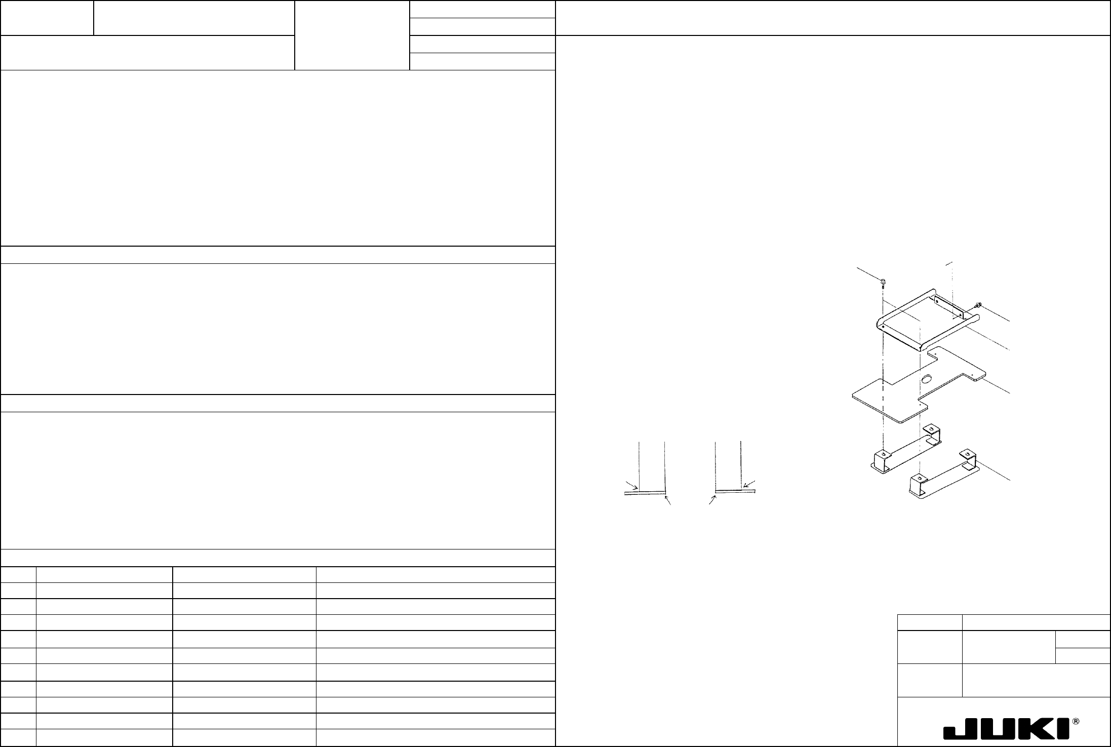
Check procedure:
When the Z-slide shaft is rotated about 360 degrees, the diffuser should not contact the nozzle outer surface.
(LAIC head only)
Turn the Z-slide shaft 360 degrees and check that the φ22.5-hole in the diffuser is not in contact with the
nozzle outer surface.
Adjustment procedure:
Temporarily secure the diffuser support to head bracket IC with SEMS cap (a). Using SEMS cap (b), install
the raxa paper base assembly to sandwich the diffuser. At this time, adjust the position of the diffuser
support to allow no clearance between the raxa paper base assembly and the bottom surface of FMLA; then
secure it in position. (See the illustration below.)
Adjust the position of the diffuser so that it does not contact the nozzle outer surface; then, secure it in
position. At this time, align the end face of the raxa paper base assembly with that of FMLA so that VCS
will not pick up the image of the bottom surface of FMLA. (See the illustration below.)
A
lign end faces.
Clearance 0
Clearance 0
Raxa paper base
assembly
E3219725OAO
(Make sure there
are RH and LH.)
Diffuser
E3213735000
Diffuser support
E3214725000
(a) SEMS cap x2
SL6040692TN
Bracket IC
(b) SEMS cap x4
SL6031092TN
– Damaged diffuser
FUNCTION NAME Lens Length Function/Performance CHECK/ADJUSTMENT METHODS (REMEDIAL ACTION PROCEDURE)
ASSURED QUALITY Reliability
QUALITY CHARACTERISTICS (SPECIFICATION VALUES) CATEGORY Safety
Product Image
ROLE IN FUNCTION (MEANING OF SPECIFICATION VALUES)
POSSIBLE MALFUNCTIONS (CAUSED BY INCORRECT SPECIFICATION VALUES)
COMPONENTS
NO. Part No. Part Name Associated Quality Characteristics
1 E9618721000 Lens
2
3 MODEL KE-750/760
4
UNIT Head
REF. NO.
5
NAME
23
6
FUNCTION Lens Length
7
NAME
8
9
10
QA Table
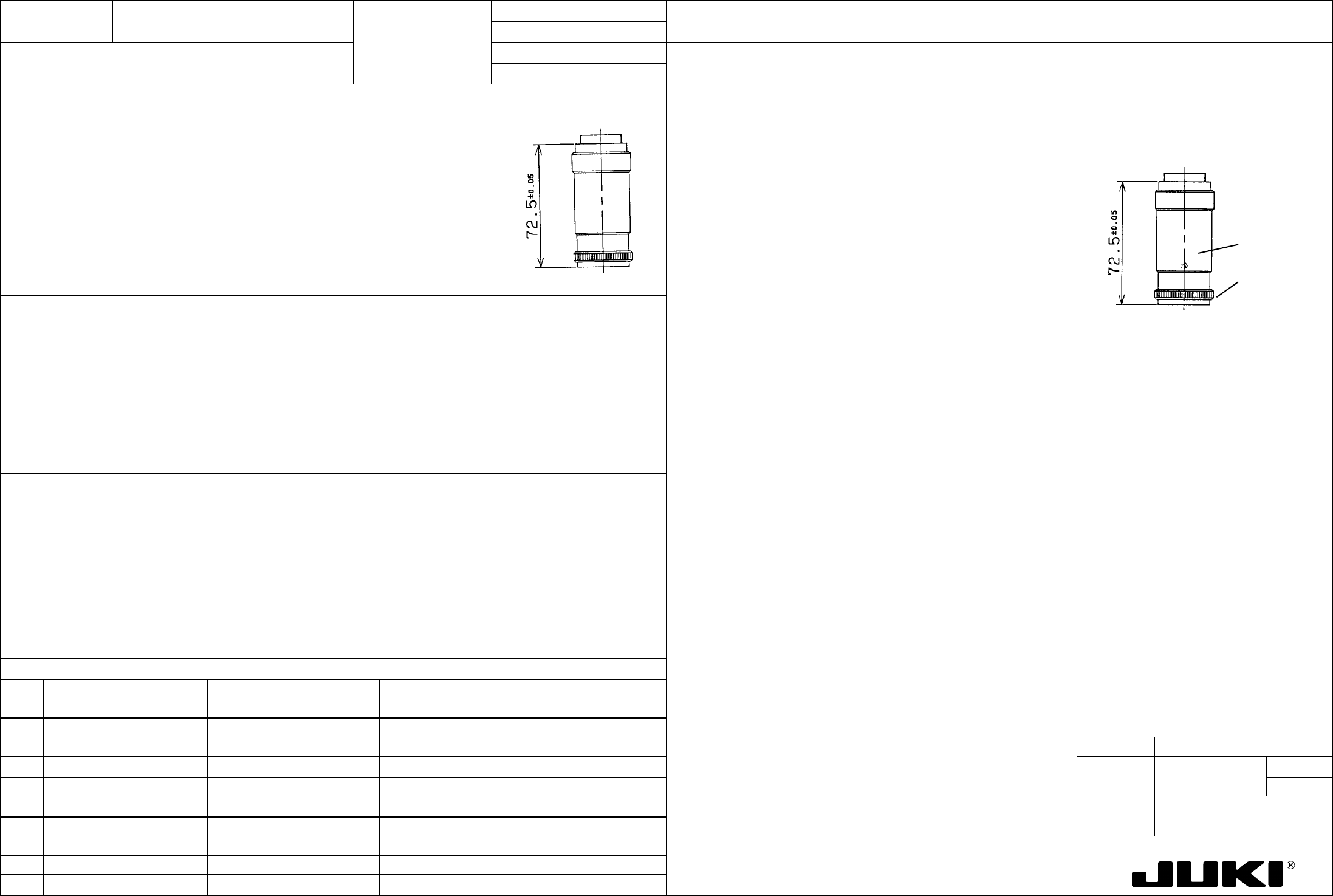
Loosen screws (a) (at three places) and turn the knob on the end so that the lens becomes 72.5 ±0.05 mm in
length.
Lens length: 72.5 ±0.05 mm
(a)
Knob
Determines the magnification of the camera to obtain the required field of view.
– Narrow field of view
– Degraded recognition accuracy