KE-750_QA表.pdf - 第27页
FUNCTION NAME Focus Adjustment F unction/Performance CHECK/ADJUSTMENT MET HODS (REMEDIAL ACTION PROCEDURE) ASSURED QUALITY Reliability QUALITY CHARACTERISTI CS (SPECIFIC ATION VALUES) CATEGORY Safety Product Image ROLE I…
FUNCTION NAME Lens Length Function/Performance CHECK/ADJUSTMENT METHODS (REMEDIAL ACTION PROCEDURE)
ASSURED QUALITY Reliability
QUALITY CHARACTERISTICS (SPECIFICATION VALUES) CATEGORY Safety
Product Image
ROLE IN FUNCTION (MEANING OF SPECIFICATION VALUES)
POSSIBLE MALFUNCTIONS (CAUSED BY INCORRECT SPECIFICATION VALUES)
COMPONENTS
NO. Part No. Part Name Associated Quality Characteristics
1 E9618721000 Lens
2
3 MODEL KE-750/760
4
UNIT Head
REF. NO.
5
NAME
23
6
FUNCTION Lens Length
7
NAME
8
9
10
QA Table
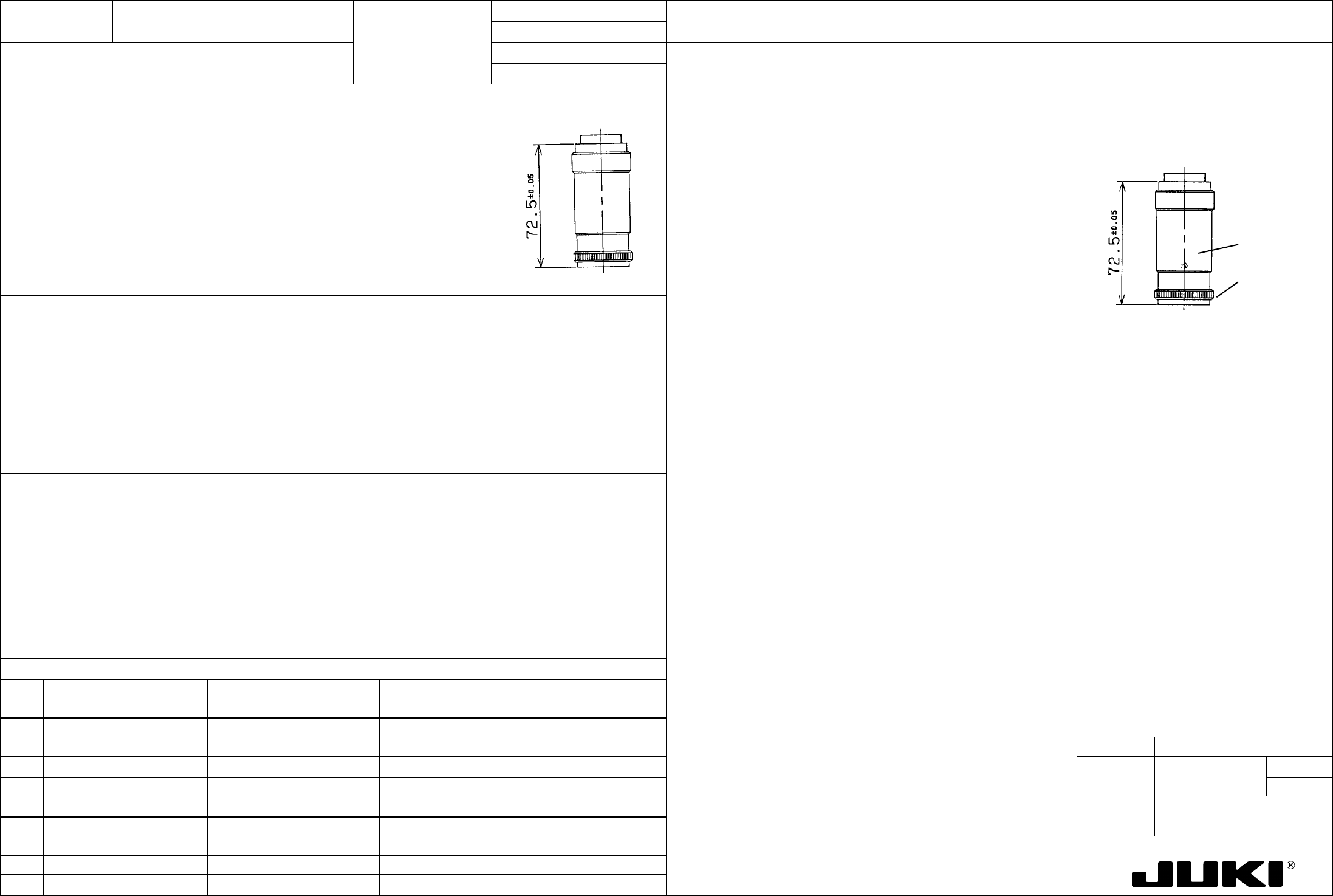
Loosen screws (a) (at three places) and turn the knob on the end so that the lens becomes 72.5 ±0.05 mm in
length.
Lens length: 72.5 ±0.05 mm
(a)
Knob
Determines the magnification of the camera to obtain the required field of view.
– Narrow field of view
– Degraded recognition accuracy
FUNCTION NAME Focus Adjustment Function/Performance CHECK/ADJUSTMENT METHODS (REMEDIAL ACTION PROCEDURE)
ASSURED QUALITY Reliability
QUALITY CHARACTERISTICS (SPECIFICATION VALUES) CATEGORY Safety
Product Image
ROLE IN FUNCTION (MEANING OF SPECIFICATION VALUES)
POSSIBLE MALFUNCTIONS (CAUSED BY INCORRECT SPECIFICATION VALUES)
COMPONENTS
NO. Part No. Part Name Associated Quality Characteristics
1 E38017250A0 Camera unit assembly
2
3 MODEL KE-750/760
4
UNIT Head
REF. NO.
5
NAME
24
6
FUNCTION Focus Adjustment
7
NAME
8
9
10
QA Table
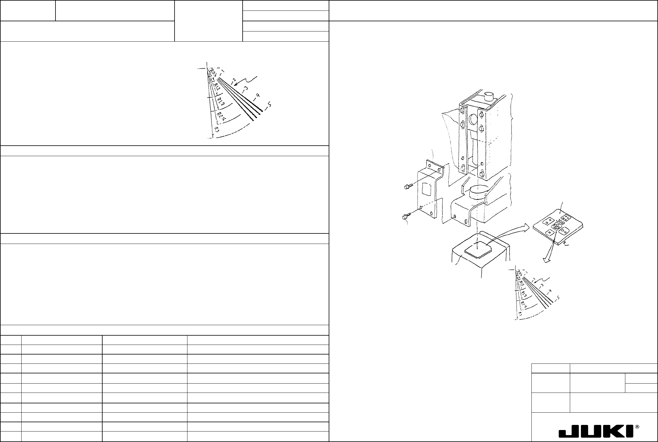
Place the camera adjustment jig on the top surface of the calibration block, facing its etching surface down.
Lines up to 2 on the etching surface of the camera adjustment jig must be clearly visible.
Loosen six SEMS cap bolts (1) that secure the camera, move the camera up and down, and when lines up to 2
on the etching surface are clearly visible, secure the camera in position.
Lines up to 2 must be
clearly visible.
Lines up to 2
must be visible
Etching surface
(back side)
Camera adjustment jig
T110
Light unit L assembl
y
E3811725OAO
Light unit R assembly
E3821725OAO
Camera unit assembl
y
E3801725OAO
Calibration bloc
k
SEMS cap x2
SL6030692TN
SEMS cap x2
SL6030692TN
Camera bracket D
E3809725000
SEMS cap (1)
(SL6041092TN)
Concerned with camera recognition accuracy, it greatly affects placement accuracy and component pickup
reliability.
– Degraded placement accuracy when BOC mark is used
– Degraded bank recognition accuracy and teaching accuracy, resulting in poorer pickup reliability
FUNCTION NAME Sensor Height Function/Performance CHECK/ADJUSTMENT METHODS (REMEDIAL ACTION PROCEDURE)
ASSURED QUALITY Reliability
QUALITY CHARACTERISTICS (SPECIFICATION VALUES) CATEGORY Safety
Product Image
ROLE IN FUNCTION (MEANING OF SPECIFICATION VALUES)
POSSIBLE MALFUNCTIONS (CAUSED BY INCORRECT SPECIFICATION VALUES)
COMPONENTS
NO. Part No. Part Name Associated Quality Characteristics
1
2
3 MODEL KE-750/760
4
UNIT Bad Mark Sensor
REF. NO.
5
NAME
25
6
FUNCTION Sensor Height
7
NAME
8
9
10
QA Table
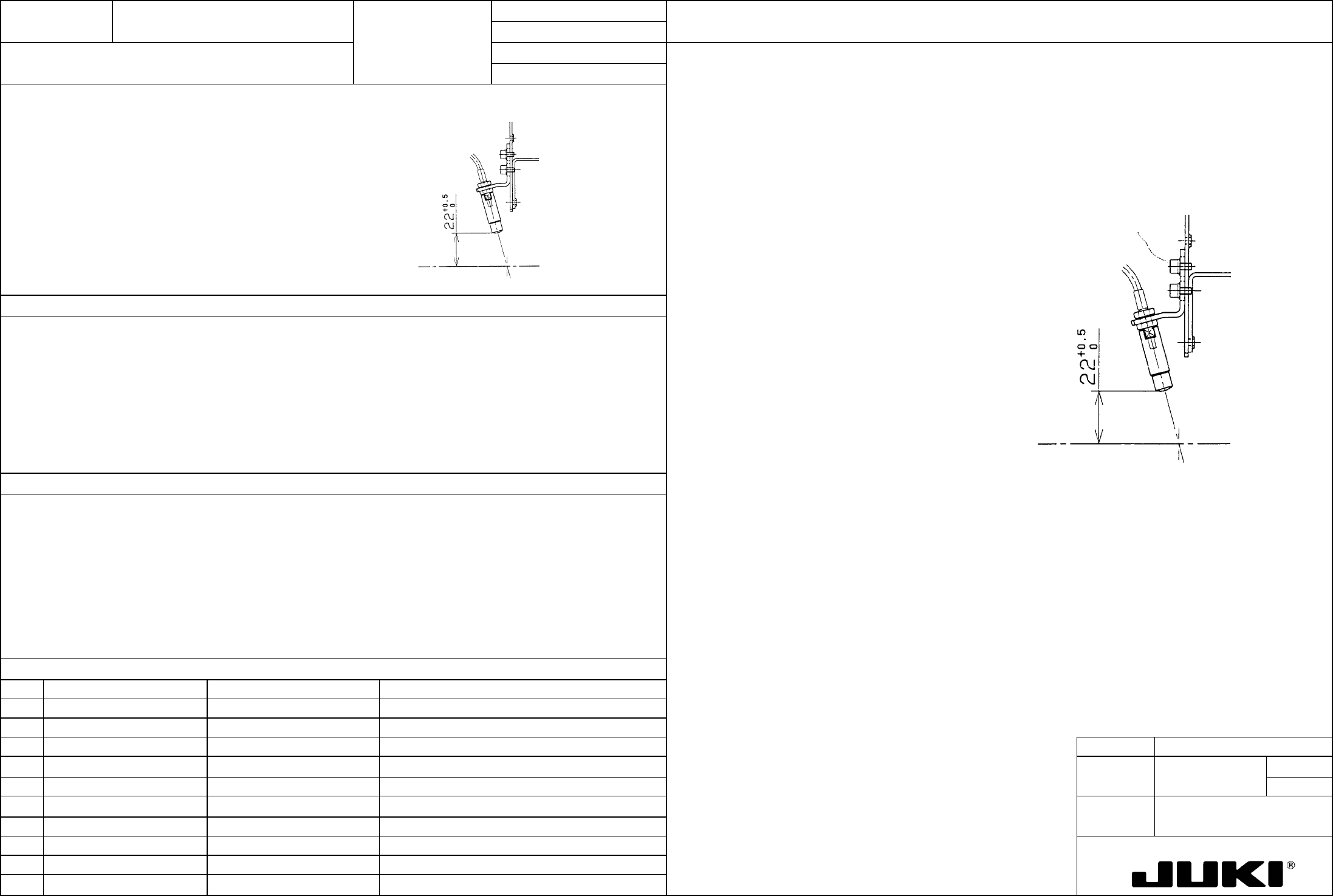
Move the bad mark sensor to a point above the calibration block. Loosen the SEMS cap bolts (a) at two places
and move the BM lens holder so that the distance between the bottom surface of the bad mark sensor and top
surface of calibration block becomes 22 +0.5/0 mm. When the specified distance is reached, secure the bad
mark sensor with SEMS cap bolts (a).
Distance between the bottom surface of bad mark sensor and top surface of calibration block: 22 +0.5/0 mm
Calibration bloc
k
top surface
SEMS cap (a)
– Bad mark detection error
– Contact with a 20-mm-high component