KE-750_QA表.pdf - 第34页
FUNCTION NAME Positioning of Pin Referenc e PWB Function/Performance CHECK/ADJUSTMENT METHODS (REMEDIAL ACTION PROCEDURE) ASSURED QUALITY Reliability QUALITY CHARACTERISTI CS (SPECIFIC ATION VALUES) CATEGORY Safety Produ…
FUNCTION NAME BU Table Up-and-Down Movement Function/Performance CHECK/ADJUSTMENT METHODS (REMEDIAL ACTION PROCEDURE)
ASSURED QUALITY Reliability
QUALITY CHARACTERISTICS (SPECIFICATION VALUES) CATEGORY Safety
Product Image
ROLE IN FUNCTION (MEANING OF SPECIFICATION VALUES)
POSSIBLE MALFUNCTIONS (CAUSED BY INCORRECT SPECIFICATION VALUES)
COMPONENTS
NO. Part No. Part Name Associated Quality Characteristics
1 E2194721000 BU damper collar
2 NM6080003SC 2113 hexagon nut
3 E2176721000 Rail guide shaft MODEL KE-750/760
4 SM8040502TP 2176 set screw UNIT Transport REF. NO.
5 PC012601000 BU table cylinder speed controller
NAME
4
6 E2019725000 Side beam FUNCTION BU Table Up-and-Down
7 E20407250A0 Transport rail F assembly
NAME Movement
8 E20707250A0 Transport rail R assembly
9
10
QA Table
UP speed adjustmen
t
A
djusting scre
w
Fixing scre
w
DOWN speed
adjustment
Shock absorber nut
BU damper colla
r
Rail guide shaft
Rail guide surface on which PWB
guide is mounted
SM8040502TP (rail guide shaft
adjusting screw)
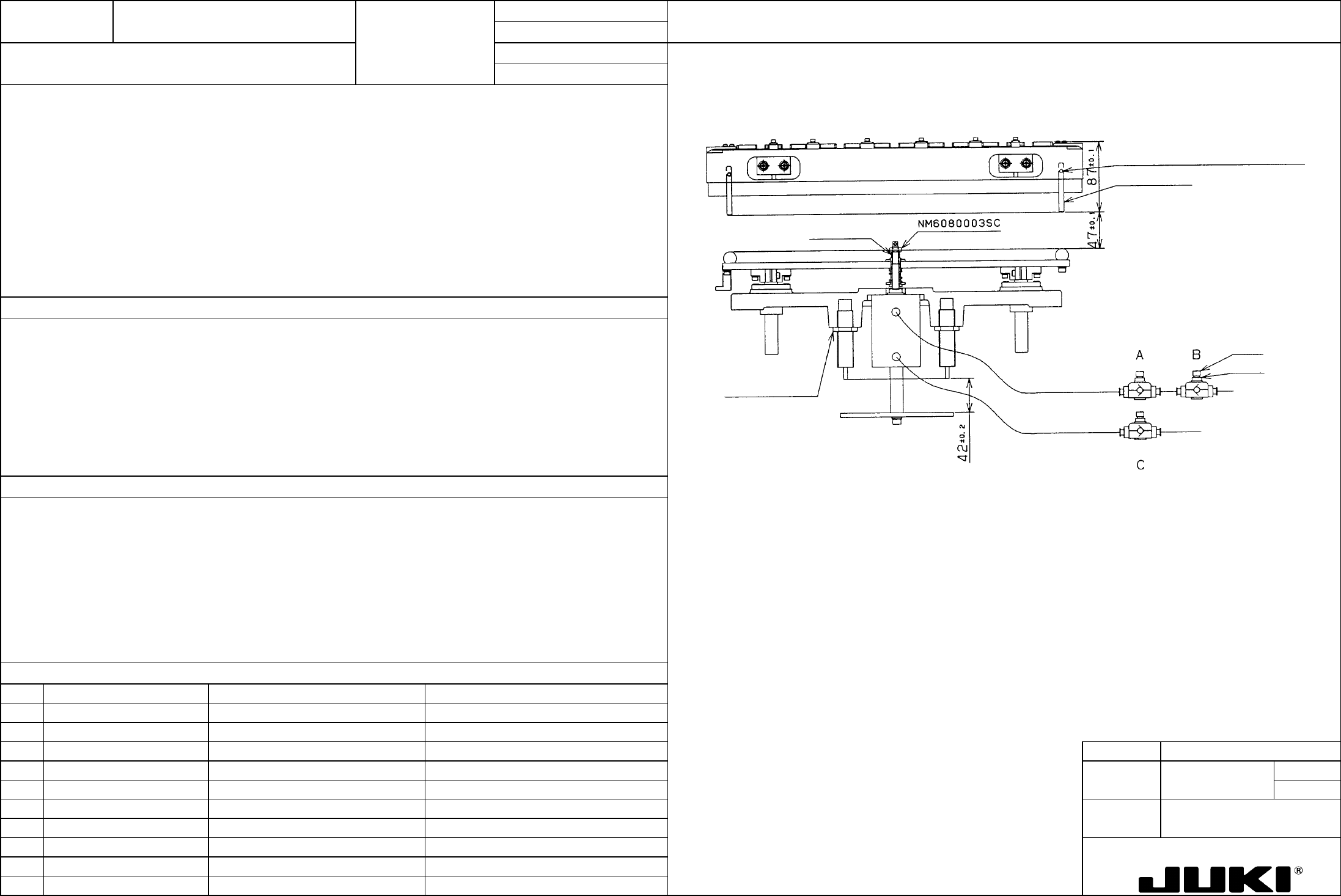
1. BU table lowest point (initial position): 47 ±0.1 (See Fig. on the right.)
2. Shock absorber orifice adjustment: Dial 6.5 (See Fig. on the right.)
3. Shock absorber height adjustment: 42 ±0.2 (See Fig. on the right.)
4. BU table cylinder speed controller adjustment
UP: From the point at which solenoid is energized to point at which UP sensor is activated: 700 ms ±20 ms
Observation point on PWB:
Solenoid energized -> TP6 (red)
UP sensor activated -> TP2 (white)
DOWN: From the point at which solenoid is deenergized to point at which DOWN sensor is activated: 600 ms ±20 ms
Observation point on PWB:
Solenoid deenergized -> TP6 (red)
DOWN sensor activated -> TP4 (white)
Adjust speed controller B shown on the right to prevent the table from suddenly falling down at the start of its downward motion.
5. Rail guide shaft height: 87 ア0.1 (See Fig. on the right.)
1. BU table up-and-down movement reference position
2, 3. Degree of shock absorbing upon collision between BU table and rail guide shaft
4. Degree of shock absorbing at PWB clamping. Transport tact time adjustment. Shock absorbing during downward motion of
BU table.
5. Transport rail raising height adjustment.
1. Too high: Guide block interfering with damper plate. The reference pin protrudes a lot from the reference hole.
Too low: The transport rail does not clamp the PWB. The BU pin does not reach the PWB. The reference pin is shallow in the
reference hole.
– BU table height adjustment: Loose NM6080003SC and turn the BU damper collar to adjust the height of the table.
– BU table cylinder speed adjustment: Turn down or back off the adjusting screw. After the adjustment has been made,
secure the fixing nut with pliers or similar tool.
2, 3. Orifice too wide, absorber too high: The table collides with the rail severely, deviating the components on the PWB.
Orifice too narrow, absorber too low: The table moves up at a very slow speed, resulting in greater transport tact time.
4. Table speed too high: The table collides with the rail guide shaft severely, deviating components on the PWB.
Table speed too low: Increased transport tact time.
5. Too high: Increased PWB clamping pressure. BU pin pushing up PWB.
Too low: The transport rail does not clamp the PWB. The BU pin does not reach the PWB.
FUNCTION NAME Positioning of Pin Reference PWB Function/Performance CHECK/ADJUSTMENT METHODS (REMEDIAL ACTION PROCEDURE)
ASSURED QUALITY Reliability
QUALITY CHARACTERISTICS (SPECIFICATION VALUES) CATEGORY Safety
Product Image
ROLE IN FUNCTION (MEANING OF SPECIFICATION VALUES)
POSSIBLE MALFUNCTIONS (CAUSED BY INCORRECT SPECIFICATION VALUES)
COMPONENTS
NO. Part No. Part Name Associated Quality Characteristics
1 E2145721*00 Centering pin*
2 E21357250A0 Guide block assembly
3 E20457250A0 Guide rail MODEL KE-750/760
4 E2130721000 Guide block L UNIT Transport REF. NO.
5 E2131721000 Guide block R
NAME
5
6 FUNCTION Positioning of Pin Reference
7
NAME PWB
8
9
10
QA Table
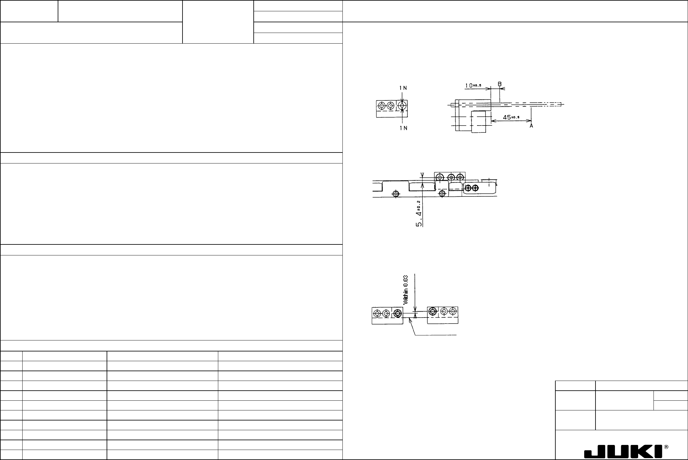
1. Play in the reference pin: 60 (m or less
1. Fix the guide block, install (4 -0.006/-0.0008 inspection bar, and apply an IN load alternately from the 180-degree opposite
direction at position B. At this time, measure play in the shaft at position A using a dial indicator.
2. Distance between the reference pin and the transport rail CF PWB guide surface: 5.4 ±0.2 mm
3. Deviation in Y-direction between the right and left reference pins: Within 0.03 mm
2. With the guide block pressed up against the transport rail side, secure the fixing screw and take measurements.
1. To maintain repeatability of PWB clamping position in the pin reference scheme.
2. To ensure good position of the reference pin with respect to the reference hole in the PWB which has been transported to
the aligning position. To provide positional reference for the PWB clamped in the pin reference scheme.
3. To provide the reference for tilt of the PWB clamped in the pin reference scheme.
3. With the guide rail mounting surface used as the reference, measure deviation in reference pin positions between guide
block L and R.
1. Repeatability of PWB clamping position in the pin reference scheme is not maintained, resulting in poor placement
accuracy.
Guide rail mounting surface
2. The reference pin does not fit into the reference hole in the PWB. Deviation in the reference pin in a placement system
that does not recognize the BOC mark results in deviation in the placement position.
3. Deviation in the reference pin in a placement system that does not recognize the BOC mark tilts the PWB, resulting in
deviation in the placement position.
FUNCTION NAME IN/OUT Sensor Board Detection Function/Performance CHECK/ADJUSTMENT METHODS (REMEDIAL ACTION PROCEDURE)
ASSURED QUALITY Reliability
QUALITY CHARACTERISTICS (SPECIFICATION VALUES) CATEGORY Safety
Product Image
ROLE IN FUNCTION (MEANING OF SPECIFICATION VALUES)
POSSIBLE MALFUNCTIONS (CAUSED BY INCORRECT SPECIFICATION VALUES)
COMPONENTS
NO. Part No. Part Name Associated Quality Characteristics
1 E94637250A0 IN sensor cable assembly
2 E94677250A0 OUT sensor cable assembly
3 SL6031292TN 9463, 9467 SEMS cap MODEL KE-750/760
4 E2094725000 Sensor bracket A UNIT Transport REF. NO.
5 E2095725000 Sensor bracket B
NAME
6
6 SL6031092TN 2094, 2095 SEMS cap FUNCTION IN/OUT Sensor Board Detection
7 E2093725000 BU sensor plate
NAME
8
9
10
QA Table
BU sensor plate
Reference-
side rail
OUT sensor cable
assembly
OUT senso
r
Sensor bracket A
SL6031092TN
Sensor position
adjusting screw
IN sensor cable
assembly
Sensor bracket B
IN senso
r
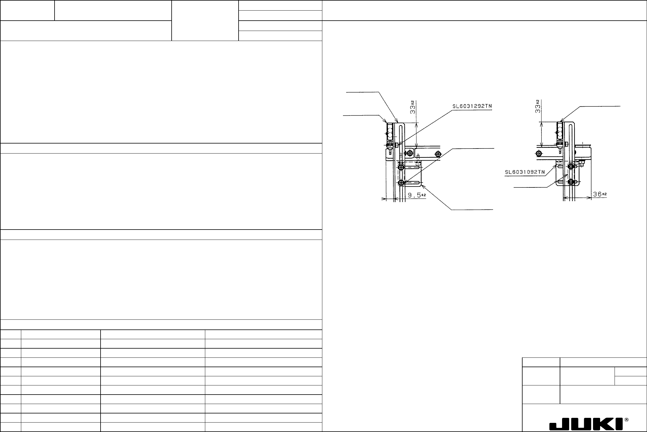
1. IN sensor adjustment position: 33 ±2 x 9.5 ±2 (See Fig. on the right.)
2. OUT sensor adjustment position: 33 ±2 x 36 ±2 (See Fig. on the right.)
1. IN motor start trigger generation timing (when transporting PWBs from an upstream machine to the local placer).
PWB width direction detection position adjustment (for PWBs of irregular shapes).
2. OUT motor stop signal trigger generation timing.
PWB width direction detection position adjustment (for PWBs of irregular shapes).
*Shows where the transport direction is from left to right:
In a configuration of left-to-right transportation, the IN sensor and OUT sensor are located in reverse way, just the opposite
to what is shown above.
With rear end reference, the sensor is mounted on the movable rail.
1. If the IN motor is late to start, it results in the PWB transport tact time increasing. (Solution: IN sensor 9.5 -> Make
smaller.)
An incoming PWB binds to oscillate on the transport belt, deviating components on it. (Solution: IN sensor 9.5 -> Make
smaller.)
2. Slow to stop: An overrun to a downstream machine. (Solution: OUT sensor 36 -> Make larger.)
Quick to stop: Increased transport tact time, insufficient feed downstream the line. (Solution: OUT sensor 36 -> Make
larger.)