KE-750_QA表.pdf - 第36页
FUNCTION NAME Stopping the PWB Being Trans ported Function/Performance CHECK/ADJUSTM ENT MET HODS (REMEDIAL ACTION PROCEDURE) ASSURED QUALITY Reliability QUALITY CHARACTERISTI CS (SPECIFIC ATION VALUES) CATEGORY Safety P…
FUNCTION NAME IN/OUT Sensor Board Detection Function/Performance CHECK/ADJUSTMENT METHODS (REMEDIAL ACTION PROCEDURE)
ASSURED QUALITY Reliability
QUALITY CHARACTERISTICS (SPECIFICATION VALUES) CATEGORY Safety
Product Image
ROLE IN FUNCTION (MEANING OF SPECIFICATION VALUES)
POSSIBLE MALFUNCTIONS (CAUSED BY INCORRECT SPECIFICATION VALUES)
COMPONENTS
NO. Part No. Part Name Associated Quality Characteristics
1 E94637250A0 IN sensor cable assembly
2 E94677250A0 OUT sensor cable assembly
3 SL6031292TN 9463, 9467 SEMS cap MODEL KE-750/760
4 E2094725000 Sensor bracket A UNIT Transport REF. NO.
5 E2095725000 Sensor bracket B
NAME
6
6 SL6031092TN 2094, 2095 SEMS cap FUNCTION IN/OUT Sensor Board Detection
7 E2093725000 BU sensor plate
NAME
8
9
10
QA Table
BU sensor plate
Reference-
side rail
OUT sensor cable
assembly
OUT senso
r
Sensor bracket A
SL6031092TN
Sensor position
adjusting screw
IN sensor cable
assembly
Sensor bracket B
IN senso
r
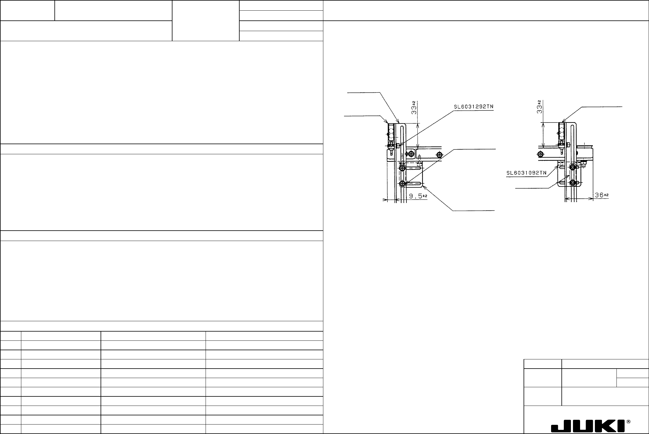
1. IN sensor adjustment position: 33 ±2 x 9.5 ±2 (See Fig. on the right.)
2. OUT sensor adjustment position: 33 ±2 x 36 ±2 (See Fig. on the right.)
1. IN motor start trigger generation timing (when transporting PWBs from an upstream machine to the local placer).
PWB width direction detection position adjustment (for PWBs of irregular shapes).
2. OUT motor stop signal trigger generation timing.
PWB width direction detection position adjustment (for PWBs of irregular shapes).
*Shows where the transport direction is from left to right:
In a configuration of left-to-right transportation, the IN sensor and OUT sensor are located in reverse way, just the opposite
to what is shown above.
With rear end reference, the sensor is mounted on the movable rail.
1. If the IN motor is late to start, it results in the PWB transport tact time increasing. (Solution: IN sensor 9.5 -> Make
smaller.)
An incoming PWB binds to oscillate on the transport belt, deviating components on it. (Solution: IN sensor 9.5 -> Make
smaller.)
2. Slow to stop: An overrun to a downstream machine. (Solution: OUT sensor 36 -> Make larger.)
Quick to stop: Increased transport tact time, insufficient feed downstream the line. (Solution: OUT sensor 36 -> Make
larger.)
FUNCTION NAME Stopping the PWB Being Transported Function/Performance CHECK/ADJUSTMENT METHODS (REMEDIAL ACTION PROCEDURE)
ASSURED QUALITY Reliability
QUALITY CHARACTERISTICS (SPECIFICATION VALUES) CATEGORY Safety
Product Image
ROLE IN FUNCTION (MEANING OF SPECIFICATION VALUES)
POSSIBLE MALFUNCTIONS (CAUSED BY INCORRECT SPECIFICATION VALUES)
COMPONENTS
NO. Part No. Part Name Associated Quality Characteristics
1 E2143721000 Stopper plate
2 E2039721000 Thrust washer
3 E2038721000 Stopper collar MODEL KE-750/760
4 UNIT Transport REF. NO.
5
NAME
7
6 FUNCTION Stopping the PWB Being
7
NAME Transported
8
9
10
QA Table
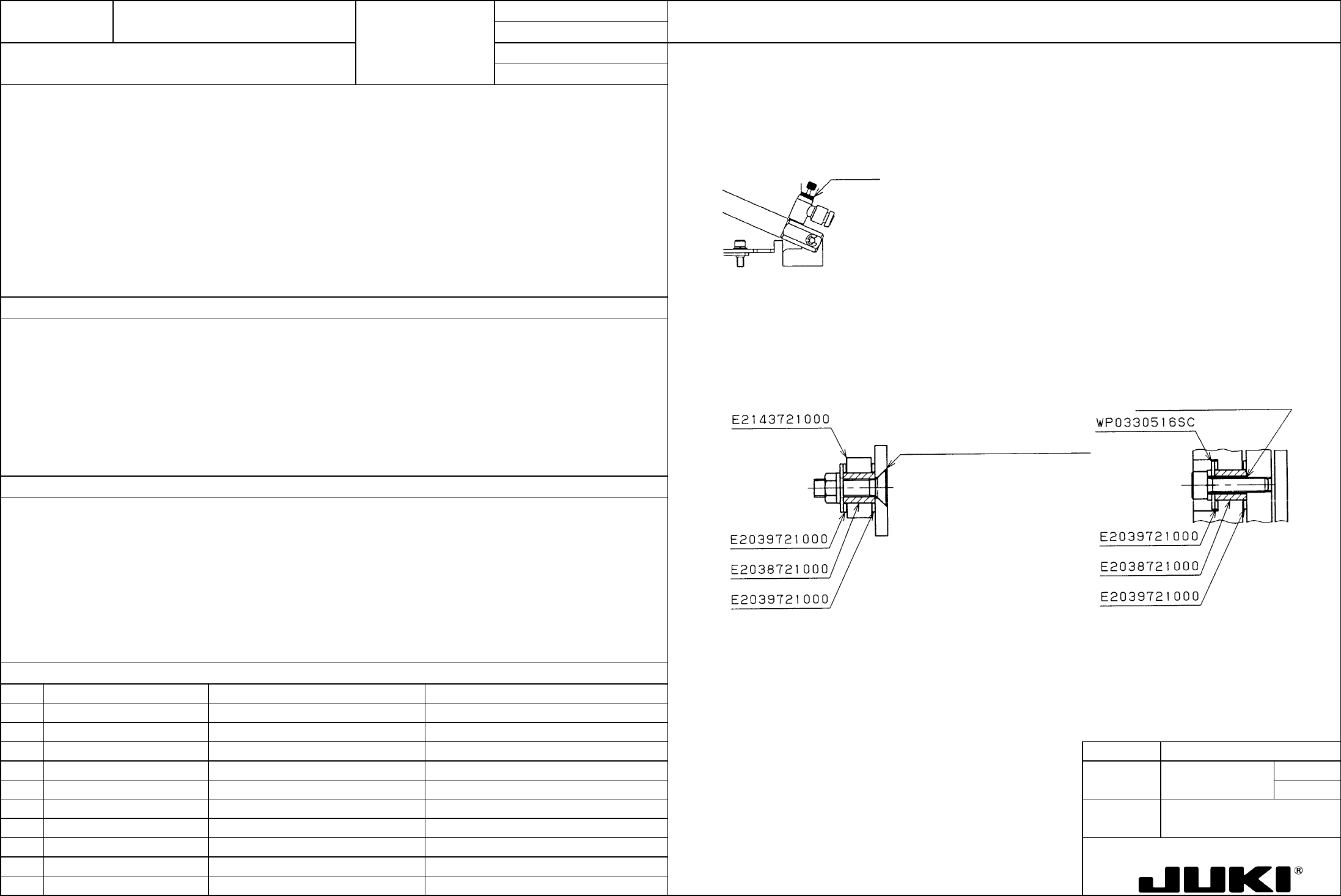
1. Speed controller opening angle: Two turns from the fully closed position.
1. Speed controller opening angle
2. The stopper plate must move smoothly.
Turn it two turns from the fully closed position and secure it in position with the lock nut.
Lock nut
2. Turn ON and OFF air to observe how the pressure plate moves. If it looks binding, check parts installed at the pivot of
the pressure plate and stopper clevis. A washer may be wedged in, a part may be missing, or the adhesive may be
squeezed out.
1. PWB clamping speed.
2. To maintain a given PWB clamping speed. To prevent interference with other parts.
Check to see i
f
adhesive is squeezed out.
Check to see if adhesive is
squeezed out on the opposite side.(stopper plate)
1. High speed: Ceramic and thin PWB cracked.
Low speed: Unable to stop the PWB at a good position.
2. The stopper frame does not move and the PWB cannot be stopped.
The stopper frame is slow to move and the PWB cannot be stopped at a good position.
FUNCTION NAME Supporting the PWB from Underside Function/Performance CHECK/ADJUSTMENT METHODS (REMEDIAL ACTION PROCEDURE)
ASSURED QUALITY Reliability
QUALITY CHARACTERISTICS (SPECIFICATION VALUES) CATEGORY Safety
Product Image
ROLE IN FUNCTION (MEANING OF SPECIFICATION VALUES)
POSSIBLE MALFUNCTIONS (CAUSED BY INCORRECT SPECIFICATION VALUES)
COMPONENTS
NO. Part No. Part Name Associated Quality Characteristics
1 E20217150A0 Backup pin assembly
2
3 MODEL KE-750/760
4 UNIT Transport REF. NO.
5
NAME
8
6 FUNCTION Supporting the PWB from
7
NAME Underside
8
9
10
QA Table
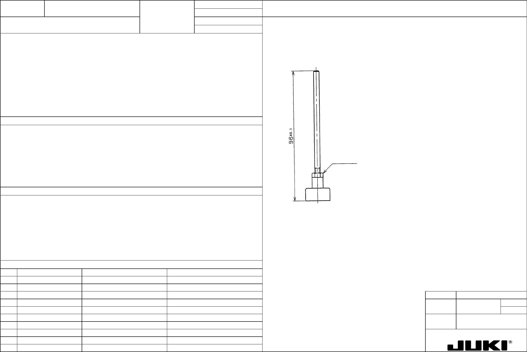
1. Loosen the adjusting nut, determine the pin height, and then secure the adjusting nut.
1. Pin height: 96 ±0.1 mm
A
djusting nut
1. Adjustment of height from BT table top surface to PWB bottom surface
1. Too high: The BU pin pushes the PWB up.
Too low: The BU pin does not reach the PWB.