KE-750_QA表.pdf - 第40页
FUNCTION NAME BU Table Up-Down Detection Function/Perfo rmance CHECK/ADJUSTMENT MET HODS (REMEDIAL ACTION PROCEDURE) ASSURED QUALITY Reliability QUALITY CHARACTERISTI CS (SPECIFICATION VALUES) CATEGORY Safety Product Ima…
FUNCTION NAME Positioning PWBs in Height Direction Function/Performance CHECK/ADJUSTMENT METHODS (REMEDIAL ACTION PROCEDURE)
ASSURED QUALITY Reliability
QUALITY CHARACTERISTICS (SPECIFICATION VALUES) CATEGORY Safety
Product Image
ROLE IN FUNCTION (MEANING OF SPECIFICATION VALUES)
POSSIBLE MALFUNCTIONS (CAUSED BY INCORRECT SPECIFICATION VALUES)
COMPONENTS
NO. Part No. Part Name Associated Quality Characteristics
1 E2044725000 Transport rail FC
2 E2073725000 Transport rail RC
3 E2074725000 Support plate C MODEL KE-750/760
4 E2061725000 Rail stand CL UNIT Transport REF. NO.
5 E2062725000 Rail stand CR
NAME
10
6 E2123721000 PWB guide plate F FUNCTION Positioning PWBs in Height
7 E2124721000 PWB guide plate RA
NAME Direction
8 E2125721000 PWB guide plate RB
9
10
QA Table
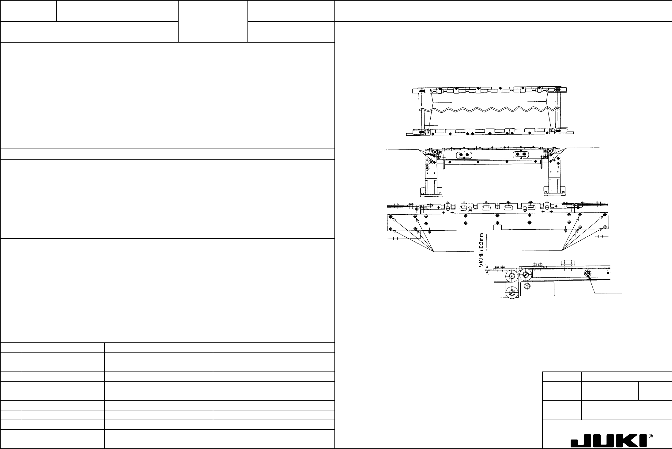
Mount a dial indicator on camera bracket D, loosen transport rail F set screws and support plate set screws, and adjust so that
the difference in height among four measurement points shown below is within 0.1 mm and that the difference in height from
the calibration block is within 0.1 mm.
1. With the BU table in the upper position, the difference in height between four points in the transport rail and calibration
block should be within 0.1 mm.
Transport rail set screw
Support plate
set screws
Support plate
set screws
Transport rail F setscrews
Transport rail F set screws
Measurement point
s
Measurement points
The calibration block serves as the reference for components placement in the height direction. Aligning the reference
surface height with the block ensures good component release height of the head.
If the distance between the point of component release and the PWB surface on which the component lands is too wide, the
head tends to throw the component away, resulting in poor placement accuracy.
If the height of the transport rail FC and RC has been changed, check the difference in height from the transport pulley at the
end of the IN and OUT transport rails.
Adjust the transport rail height so that the step difference measures within 0.2 mm (at four places).
FUNCTION NAME BU Table Up-Down Detection Function/Performance CHECK/ADJUSTMENT METHODS (REMEDIAL ACTION PROCEDURE)
ASSURED QUALITY Reliability
QUALITY CHARACTERISTICS (SPECIFICATION VALUES) CATEGORY Safety
Product Image
ROLE IN FUNCTION (MEANING OF SPECIFICATION VALUES)
POSSIBLE MALFUNCTIONS (CAUSED BY INCORRECT SPECIFICATION VALUES)
COMPONENTS
NO. Part No. Part Name Associated Quality Characteristics
1 HD000760000 BU table sensor
2 SM403101SC HD04 set screw
3 E2093725000 BU sensor plate MODEL KE-750/760
4 E2092725000 BU sensor stay UNIT Transport REF. NO.
5 SL6051292TN 2092 SEMS cap
NAME
11
6 E2008725000 BU dog FUNCTION BU Table Up-Down Detection
7 SL6041092TN 2008 SEMS cap
NAME
8
9
10
QA Table
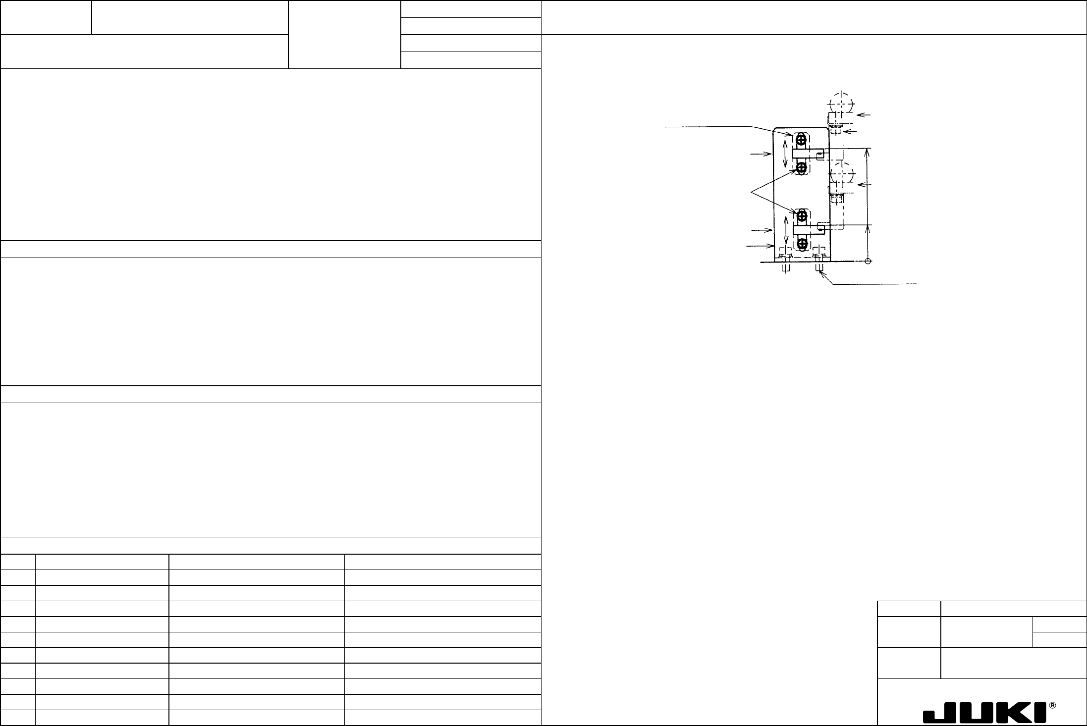
2092 SEMS cap
26 (temporary fixing position)
BU table DOWN position
81 (temporary fixing position)
BU dog
BU table UP position
BU sensor sta
y
BU table sensor (DOWN)
HD00 set scre
w
BU table sensor (UP)
BU sensor plate
1. Adjusting the height of BU table sensor (UP):
With a 4.5ア0.1-mm-thick plate clamped, gradually lower the BU table sensor (UP) and, when the sensor is activated,
secure it in position.
2. Adjusting the height of BU table sensor (DOWN):
With the BU table in the lowered position, gradually raise the BU table sensor (UP) and, when the sensor is activated,
move the sensor up another 1 mm and secure it at that position.
3. Adjusting the positional reference between BU dog and BU table sensor:
Secure the BU dog in the BU table sensor slit where it does not contact the sensor.
1. BU table upward motion detection
2. BU table downward motion detection
3. To meet the BU dog shielding function.
1. Sensor located too high: Unable to detect a table going up -> The system is unable to proceed with the next process
(timeout error). [Solution: Lower the BU table sensor (UP).]
Sensor located too low: Pusher operates too quickly. -> PWB clamping failure [Solution: Raise the BU table sensor
(UP).]
2. Sensor located too high: CENT transport starts too early. -> PWB failing to ride on OUT buffer [Solution: Lower the BU
table sensor (DOWN).]
Sensor located too low: Unable to detect a table going down -> The system is unable to proceed with the next process
(timeout error). [Solution: Raise the BU table sensor (DOWN).]
3. BU dog detection error: The system is unable to proceed with the next process (timeout error). [Solution: Adjust dog
position; adjust BU sensor stay position.]
FUNCTION NAME Feeding PWBs Smoothly - 1 Function/Performance CHECK/ADJUSTMENT METHODS (REMEDIAL ACTION PROCEDURE)
ASSURED QUALITY Reliability
QUALITY CHARACTERISTICS (SPECIFICATION VALUES) CATEGORY Safety
Product Image
ROLE IN FUNCTION (MEANING OF SPECIFICATION VALUES)
POSSIBLE MALFUNCTIONS (CAUSED BY INCORRECT SPECIFICATION VALUES)
COMPONENTS
NO. Part No. Part Name Associated Quality Characteristics
1 E2044725000 Transport rail FC
2 E2073725000 Transport rail RC
3 E2049725000 Transport rail MODEL KE-750/760
4 E2041725000 PWB guide U UNIT Transport REF. NO.
5 E2042725000 PWB guide L
NAME
12
6 E2046725000 PWB inner FUNCTION Feeding PWBs Smoothly - 1
7
NAME
8
9
10
QA Table
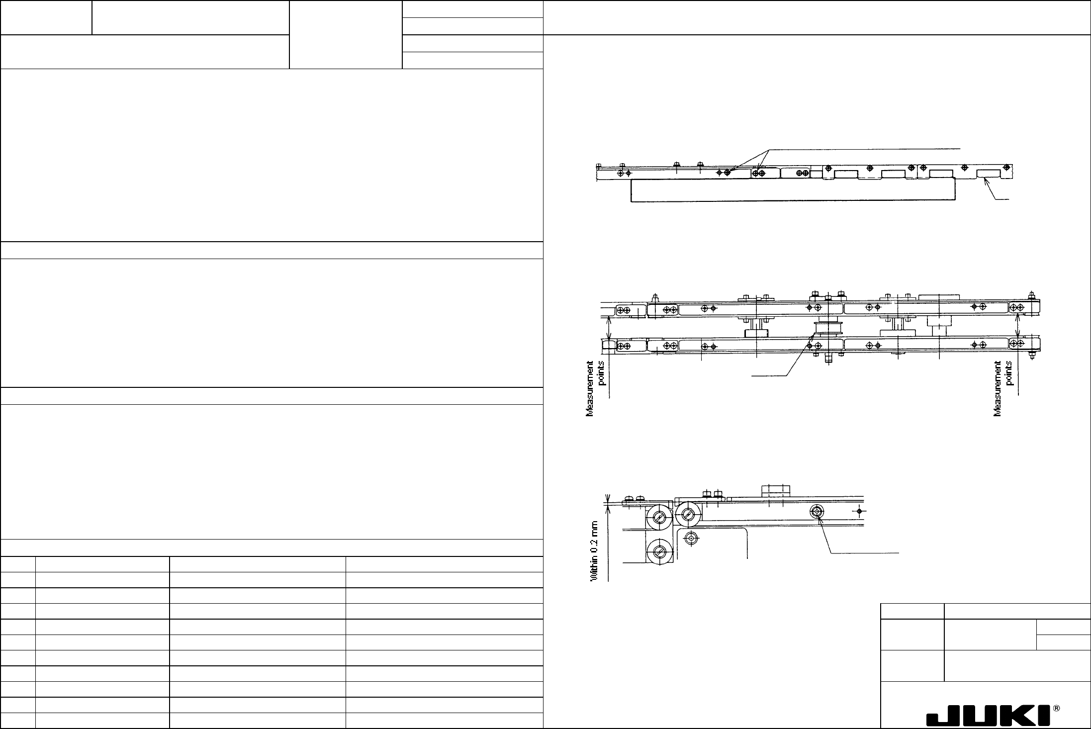
1. Transport rail straightness
1. Transport rail installed straightness: -|0.3
Apply a ruler with reference to transport rail FC and RC and place the PWB guide along the ruler.
2. Transport rail parallelism between F and R: //|0.5
3. Ride-over step between transport rails: Within 0.2 mm
Reference
Loosen screws and determine positions o
f
PWB guide and inner along the ruler.
2. Transport rail parallelism
Take measurements of rail width at four places in the transport direction and adjust the rail width so that the difference
between the maximum and minimum measurements is within 0.5 mm. Measure rail width for 30 mm and 254 mm. For
rail width 30 mm, press the end face of pulley A against the end face of screw shaft nut to serve as the limit.
Two measurement points at the symmetrical
positions on the opposite end
Pulley A
Guides the PWB straight along its path as it is being transported.
1. The PWB is get caught at the rail joint, resulting in the components being deviated from their correct positions.
3. Ride-over step between transport rails
2. PWB binds in mid-point of transport, or runs off the rails.
Match the height of right and left transport rails with reference to the height of the belt surface of transport rail CF and CR.
3. PWB stumbles on a step, resulting in the components being deviated from their correct positions.
Transport rail set scre
w