KE-750_QA表.pdf - 第42页
FUNCTION NAME PWB X-Direction Clamp Function/Performance CHECK/ADJUSTMENT METHODS (REMEDIAL ACTION PROCEDURE) ASSURED QUALITY Reliability QUALITY CHARACTERISTI CS (SPECIFICATION VALUES) CATEGORY Safety Product Image ROLE…
FUNCTION NAME Feeding PWBs Smoothly - 1 Function/Performance CHECK/ADJUSTMENT METHODS (REMEDIAL ACTION PROCEDURE)
ASSURED QUALITY Reliability
QUALITY CHARACTERISTICS (SPECIFICATION VALUES) CATEGORY Safety
Product Image
ROLE IN FUNCTION (MEANING OF SPECIFICATION VALUES)
POSSIBLE MALFUNCTIONS (CAUSED BY INCORRECT SPECIFICATION VALUES)
COMPONENTS
NO. Part No. Part Name Associated Quality Characteristics
1 E2044725000 Transport rail FC
2 E2073725000 Transport rail RC
3 E2049725000 Transport rail MODEL KE-750/760
4 E2041725000 PWB guide U UNIT Transport REF. NO.
5 E2042725000 PWB guide L
NAME
12
6 E2046725000 PWB inner FUNCTION Feeding PWBs Smoothly - 1
7
NAME
8
9
10
QA Table
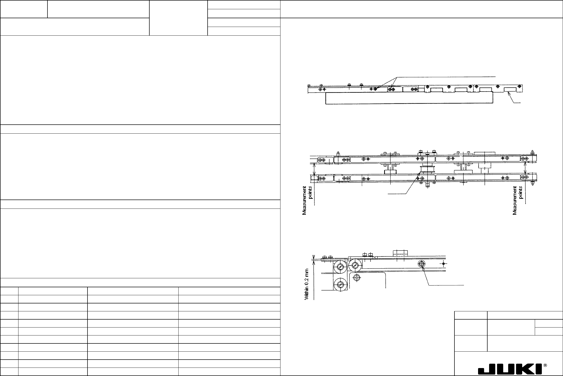
1. Transport rail straightness
1. Transport rail installed straightness: -|0.3
Apply a ruler with reference to transport rail FC and RC and place the PWB guide along the ruler.
2. Transport rail parallelism between F and R: //|0.5
3. Ride-over step between transport rails: Within 0.2 mm
Reference
Loosen screws and determine positions o
f
PWB guide and inner along the ruler.
2. Transport rail parallelism
Take measurements of rail width at four places in the transport direction and adjust the rail width so that the difference
between the maximum and minimum measurements is within 0.5 mm. Measure rail width for 30 mm and 254 mm. For
rail width 30 mm, press the end face of pulley A against the end face of screw shaft nut to serve as the limit.
Two measurement points at the symmetrical
positions on the opposite end
Pulley A
Guides the PWB straight along its path as it is being transported.
1. The PWB is get caught at the rail joint, resulting in the components being deviated from their correct positions.
3. Ride-over step between transport rails
2. PWB binds in mid-point of transport, or runs off the rails.
Match the height of right and left transport rails with reference to the height of the belt surface of transport rail CF and CR.
3. PWB stumbles on a step, resulting in the components being deviated from their correct positions.
Transport rail set scre
w
FUNCTION NAME PWB X-Direction Clamp Function/Performance CHECK/ADJUSTMENT METHODS (REMEDIAL ACTION PROCEDURE)
ASSURED QUALITY Reliability
QUALITY CHARACTERISTICS (SPECIFICATION VALUES) CATEGORY Safety
Product Image
ROLE IN FUNCTION (MEANING OF SPECIFICATION VALUES)
POSSIBLE MALFUNCTIONS (CAUSED BY INCORRECT SPECIFICATION VALUES)
COMPONENTS
NO. Part No. Part Name Associated Quality Characteristics
1 E2172715000 Pusher shaft
2 E2173715000 Thrust washer
3 E2110725000 Pusher FL MODEL KE-750/760
4 UNIT Transport REF. NO.
5
NAME
13
6 FUNCTION PWB X-Direction Clamp
7
NAME
8
9
10
QA Table
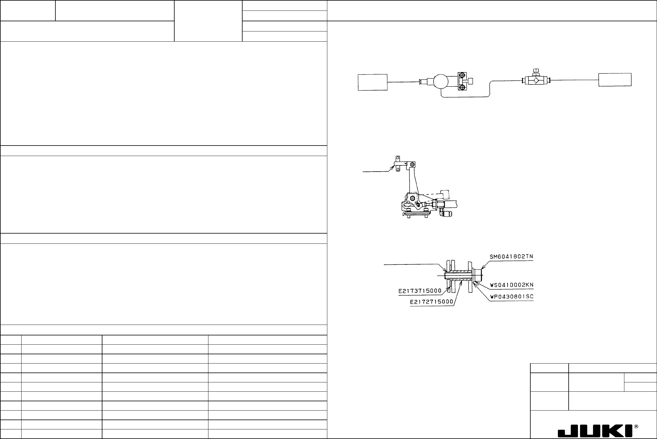
1. Reducing valve
1. Reducing valve adjustment value: 0.35 MPa
2. Pusher FL speed: From the time when solenoid is energized to when jig sensor is activated: 200 ms
ア10 ms
Pusher
X
Adjust to meet the
requirement of 2. To be
locked with lock nut.
0.35 MPa; Tobe locked
with lock nut
Solenoid
valve
3. The pusher FL must move smoothly.
2. Install the jig sensor at the position where the pusher FL rises. Connect the 3P connector of the sensor to CN7 of
CARRY board. Use TP7 (red) and TP2 (white) to determine whether the solenoid is energized and jig sensor is activated,
respectively.
A
ir OFF
Air ON
Jig senso
r
1. PWB clamping pressure in the X-direction
2. PWB clamping speed
3. To maintain a given PWB clamping speed. To prevent interference with other parts.
3. Turn ON and OFF air to observe the operation of pusher FL. If pusher FL tends to bind, check the parts at the pusher FL
pivot for installation. A washer may be wedged, a part may be missing, or adhesive may be squeezed out.
Note adhesive that is squeezed
out on the opposite end.
1. Pressure too high: A ceramic or thin PWB is cracked.
Pressure too low: Unable to move the PWB to the specified position.
2. Speed too low: Increased transport tact time. Vertical clamping occurs before X-clamping is completed.
Speed too high: A ceramic or thin PWB is cracked.
3. Pusher FL does not move, not clamping the PWB.
The pusher is slow to move and vertical clamping occurs before X-clamping is completed.
FUNCTION NAME Outline Reference Y-Direction Clamp Function/Performance CHECK/ADJUSTMENT METHODS (REMEDIAL ACTION PROCEDURE)
ASSURED QUALITY Reliability
QUALITY CHARACTERISTICS (SPECIFICATION VALUES) CATEGORY Safety
Product Image
ROLE IN FUNCTION (MEANING OF SPECIFICATION VALUES)
POSSIBLE MALFUNCTIONS (CAUSED BY INCORRECT SPECIFICATION VALUES)
COMPONENTS
NO. Part No. Part Name Associated Quality Characteristics
1 E2161721000 Pusher
2 PC0205010A0 Reducing valve
3 PC012401000 Speed controller MODEL KE-750/760
4 UNIT Transport REF. NO.
5
NAME
14
6 FUNCTION Outline Reference Y-Direction
7
NAME Clamp
8
9
10
QA Table
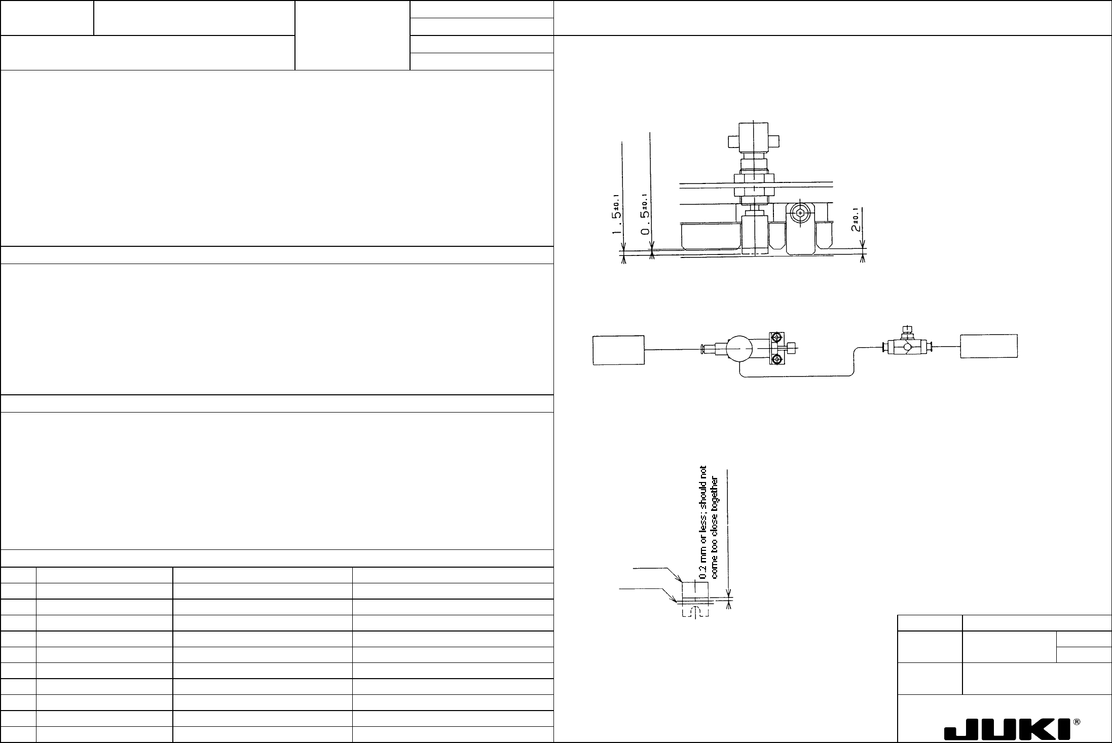
1. Measure the position of the pusher with respect to PWB guide RA and RB when air is turned ON and OFF.
1. Pusher protrusion: ON -> 1.5 mm; OFF -> 0.5 mm
2. Reducing valve: 0.5 MPa
3. Speed controller opening angle: Turned two turns from the fully closed position.
4. Clearance between pusher and transport belt: 0.2 mm or less, with no part getting too close together
5. The pusher must be moved smoothly when air is turned ON and OFF.
1. Optimum amount of push in Y-direction
2. Reducing valve, speed controller opening angle
2. Pusher Y optimum clamping pressure
3. Pusher Y optimum clamping speed
Pusher Y
Two turns from full
y
closed position; to
be locked with lock
nut.
0.5 MPa; To be locked
with lock nut
Solenoid
valve
4. To prevent pusher Y and transport belt from getting too close together
5. To prevent interference between pusher and other parts
3. A 0.2-mm feeler gage should not go into the space between the pusher and belt. The belt should not come too close
together with the pusher when driven.
1. Protrusion too much: PWB runs off PWB guide RA and RB and the system is unable to clamp it in the vertical direction.
Protrusion too little: Unable to clamp the PWB.
2, 3. Speed and pressure too high: A ceramic or thin PWB is cracked.
Pushe
r
Transport belt
Speed and pressure too low: Unable to clamp the PWB comfortably.
4. When pusher Y gets too close to the belt, the transport belt stops moving.
If pusher Y is too wide apart from the belt, a thin PWB can gets into the clearance.
5. Interference between pusher and other parts.