KE-750_QA表.pdf - 第44页
FUNCTION NAME Stabilization of Movable Rail Function/Perform ance CHECK/ADJUSTMENT METHODS (REMEDIAL ACTION PROCEDURE) ASSURED QUALITY Reliability QUALITY CHARACTERISTI CS (SPECIFICATION VALUES) CATEGORY Safety Product I…
FUNCTION NAME Outline Reference Y-Direction Clamp Function/Performance CHECK/ADJUSTMENT METHODS (REMEDIAL ACTION PROCEDURE)
ASSURED QUALITY Reliability
QUALITY CHARACTERISTICS (SPECIFICATION VALUES) CATEGORY Safety
Product Image
ROLE IN FUNCTION (MEANING OF SPECIFICATION VALUES)
POSSIBLE MALFUNCTIONS (CAUSED BY INCORRECT SPECIFICATION VALUES)
COMPONENTS
NO. Part No. Part Name Associated Quality Characteristics
1 E2161721000 Pusher
2 PC0205010A0 Reducing valve
3 PC012401000 Speed controller MODEL KE-750/760
4 UNIT Transport REF. NO.
5
NAME
14
6 FUNCTION Outline Reference Y-Direction
7
NAME Clamp
8
9
10
QA Table
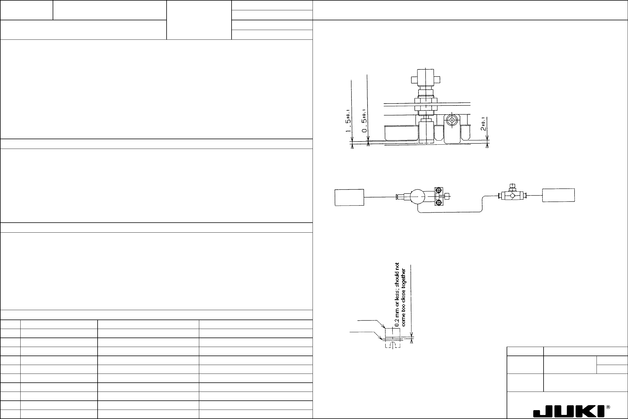
1. Measure the position of the pusher with respect to PWB guide RA and RB when air is turned ON and OFF.
1. Pusher protrusion: ON -> 1.5 mm; OFF -> 0.5 mm
2. Reducing valve: 0.5 MPa
3. Speed controller opening angle: Turned two turns from the fully closed position.
4. Clearance between pusher and transport belt: 0.2 mm or less, with no part getting too close together
5. The pusher must be moved smoothly when air is turned ON and OFF.
1. Optimum amount of push in Y-direction
2. Reducing valve, speed controller opening angle
2. Pusher Y optimum clamping pressure
3. Pusher Y optimum clamping speed
Pusher Y
Two turns from full
y
closed position; to
be locked with lock
nut.
0.5 MPa; To be locked
with lock nut
Solenoid
valve
4. To prevent pusher Y and transport belt from getting too close together
5. To prevent interference between pusher and other parts
3. A 0.2-mm feeler gage should not go into the space between the pusher and belt. The belt should not come too close
together with the pusher when driven.
1. Protrusion too much: PWB runs off PWB guide RA and RB and the system is unable to clamp it in the vertical direction.
Protrusion too little: Unable to clamp the PWB.
2, 3. Speed and pressure too high: A ceramic or thin PWB is cracked.
Pushe
r
Transport belt
Speed and pressure too low: Unable to clamp the PWB comfortably.
4. When pusher Y gets too close to the belt, the transport belt stops moving.
If pusher Y is too wide apart from the belt, a thin PWB can gets into the clearance.
5. Interference between pusher and other parts.
FUNCTION NAME Stabilization of Movable Rail Function/Performance CHECK/ADJUSTMENT METHODS (REMEDIAL ACTION PROCEDURE)
ASSURED QUALITY Reliability
QUALITY CHARACTERISTICS (SPECIFICATION VALUES) CATEGORY Safety
Product Image
ROLE IN FUNCTION (MEANING OF SPECIFICATION VALUES)
POSSIBLE MALFUNCTIONS (CAUSED BY INCORRECT SPECIFICATION VALUES)
COMPONENTS
NO. Part No. Part Name Associated Quality Characteristics
1 E2010725000 Screw shaft
2
3 MODEL KE-750/760
4 UNIT Transport REF. NO.
5
NAME
15
6 FUNCTION Stabilization of Movable Rail
7
NAME
8
9
10
QA Table
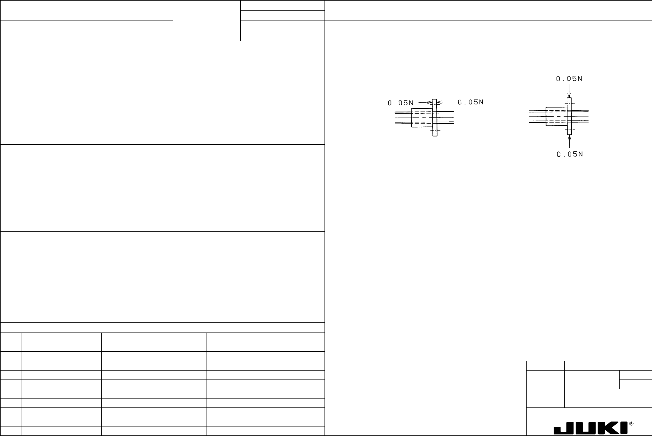
Apply a lever dial indicator to the nut. Measure the movement of the nut when a load is applied to it alternately from the
opposite directions as illustrated below.
1. The movement of the screw shaft nut should be within 50 um when a 0.05-N load is applied to it alternately from the
opposite thrust directions.
2. The movement of the screw shaft nut should be within 100 um when a 0.05-N load is applied to it alternately from the
opposite radial directions.
1, 2. To minimize play in the movable rail, thereby minimizing vibration during operation.
Thrust direction Radial direction
1, 2. When the movable rail oscillates during placement of components, it causes the PWB to oscillate, resulting in poor
placement accuracy.
FUNCTION NAME Changing the Transport Rail Width Function/Performance CHECK/ADJUSTMENT METHODS (REMEDIAL ACTION PROCEDURE)
ASSURED QUALITY Reliability
QUALITY CHARACTERISTICS (SPECIFICATION VALUES) CATEGORY Safety
Product Image
ROLE IN FUNCTION (MEANING OF SPECIFICATION VALUES)
POSSIBLE MALFUNCTIONS (CAUSED BY INCORRECT SPECIFICATION VALUES)
COMPONENTS
NO. Part No. Part Name Associated Quality Characteristics
1 E2010725000 Screw shaft
2 E2009725000 Guide shaft
3 MODEL KE-750/760
4 UNIT Transport REF. NO.
5
NAME
16
6 FUNCTION Changing the Transport Rail
7
NAME Width
8
9
10
QA Table
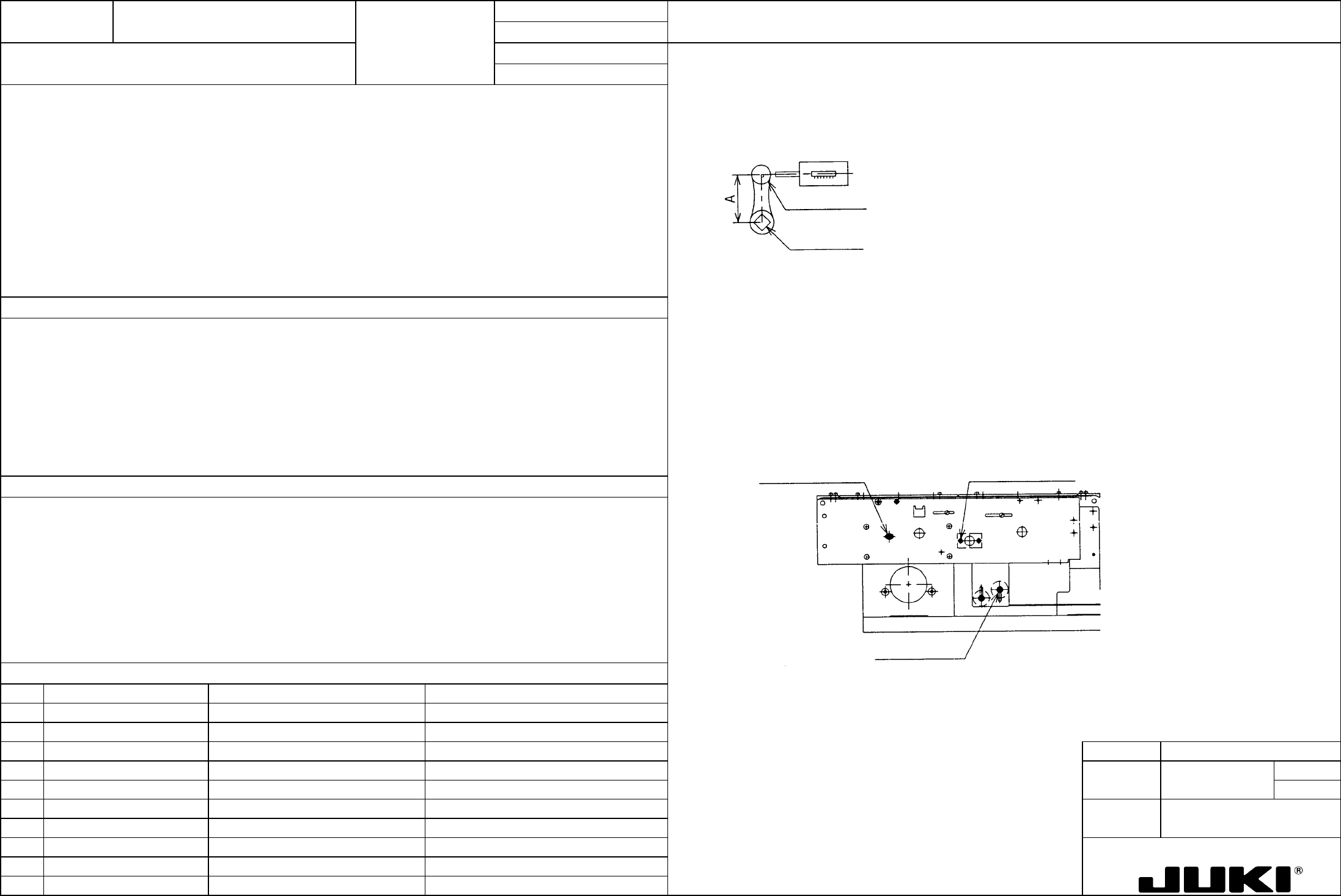
1. Apply a spring balance to the handle shaft knob and pull it in the tangential direction to measure torque in the handle shaft.
1. Handle shaft torque: 0.2 N.m or less
2. Drive belt tension: 2 to 2.5 kgf
Handle shaft axis
Handle shaft knob
Spring balance
Guide shaft parallelism adjustment:
At a 254-mm transport rail width position, fix the ball bushing position.
Loosen the screw on the end of guide shaft on the rail plate F side and tighten that screw at a 31-mm rail width position.
Screw shaft parallelism adjustment:
1. To ensure optimum torque of the PWB width adjusting handle shaft
Fix the nut position at a 254-mm PWB width position.
2. To ensure optimum tension in the timing belt that connects the right and left screw shafts
Loosen the screw on the adjust plate and tighten that screw at a 31-mm rail width position.
2. Drive belt tension
Adjust the tension by changing the height of the idler pulley. It, however, also changes the timing belt height; so be
careful about its contact with T-PIN sensor.
Take tension measurements using an acoustic wave type belt tensiometer (manufactured by Unitta).
Idler pulley set scre
w
A
djust plate set scre
w
Guide shaft end set scre
w
1. If the torque is too large, feel of operation of the rail width adjustment is not positive.
If the guide shaft and screw shaft do not run parallel, it could result in "narrow gap" and "galling" in the movable rail.
2. Tension too tight: The screw shaft flexes causing a heavy torque.
Tension too weak: Belt cogs are skipped at the pulley.