KE-750_QA表.pdf - 第49页
FUNCTION NAME X-Axis Frame Straightne ss Function/Performance CHECK/ADJUSTMENT METHODS (REMEDIAL ACT ION PROCEDURE) ASSURED QUALITY Reliability QUALITY CHARACTERISTI CS (SPECIFIC ATION VALUES) CATEGORY Safety Product Ima…
MODEL KE-750/760
UNIT X-Y Unit REF. NO.
NAME
XY-1
FUNCTION X/Y Belt Tension 2/2
NAME
QA Table
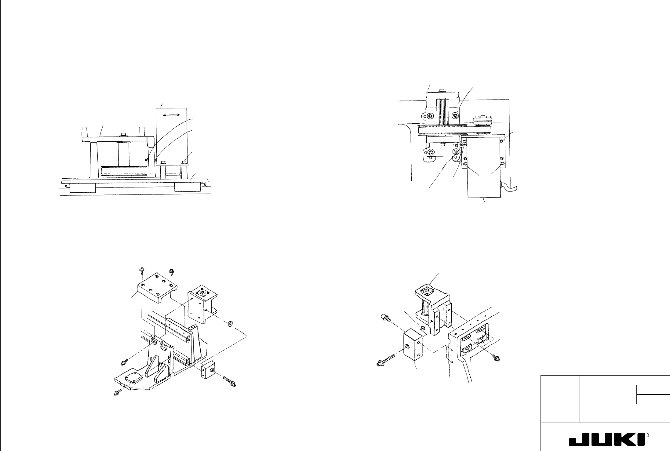
Adjustment procedure * Timing belt YA
(1) Loosen SL6061642TN that secures the YM bracket assembly.
* Timing belt XA (2) Loosen lock nut 6050001SC and turn SM8053002TP as necessary to adjust tension.
(3) After the adjustment has been made, tighten SL6061642TN to 15 Nm.
(1) Loosen SL6051492TN that secures the XM bracket assembly. (4) Tighten lock nut NM6050001SC.
(2) Loosen lock nut NM6050001SC and turn SM8053002TP as necessary to adjust tension.
SM8053002TP
NM6050001SC
YM bracket assembl
y
Straight
pins
SL6061642TN
(tightening torque 15 Nm)
YA pulley bracket assembl
y
(3) After the adjustment has been made, tighten SL6051492TN to 9 Nm.
(4) Tighten lock nut NM6050001SC.
SL6051492TN
SM8053002TP
NM6050001SC
X frame end L
XM bracket assembl
y
XA pulley bracket
assembly
* Timing belt XB
* Timing belt YB
(1) Loosen SL6061692TN that secures the XB pulley bracket assembly.
(1) Loosen SL6062592TN that secures the YB pulley bracket L and R assemblies.
(2) Loosen lock nut NM6060001SC and turn SL6065092TN as necessary to adjust tension.
(2) Loosen lock nut NM6060001SC and turn SL6065092TN as necessary to adjust tension.
(3) After the adjustment has been made, tighten SL6061692TN to 15 Nm.
(3) After the adjustment has been made, tighten SL6062592TN to 15 Nm.
(4) Tighten lock nut NM6060001SC.
(4) Tighten lock nut NM6060001SC.
XB pulley bracket assembl
y
NM6060001SC
SL6065092TN
E2407725000
X tension support
SL6061692TN
(tightening torque 15 Nm)
XB suppor
t
E2419725000
SL6065092TN
NM6060001SC
SL6062592TN
(tightening torque
15 Nm)
Y tension suppor
t
E2315725000
YB pulley bracket
L/R assembly
FUNCTION NAME X-Axis Frame Straightness Function/Performance CHECK/ADJUSTMENT METHODS (REMEDIAL ACTION PROCEDURE)
ASSURED QUALITY Reliability
QUALITY CHARACTERISTICS (SPECIFICATION VALUES) CATEGORY Safety
Product Image
ROLE IN FUNCTION (MEANING OF SPECIFICATION VALUES)
POSSIBLE MALFUNCTIONS (CAUSED BY INCORRECT SPECIFICATION VALUES)
COMPONENTS
NO. Part No. Part Name Associated Quality Characteristics
1 E2402725000 X-axis frame
2 E2403725000 LM guide X
3 E2404725000 Back plate MODEL KE-750/760
4 E2406725000 X frame end L UNIT X-Y Unit REF. NO.
5 E2406725000 X frame end R
NAME
XY-2
6 FUNCTION X-Axis Frame Straightness
7
NAME
8
9
10
QA Table
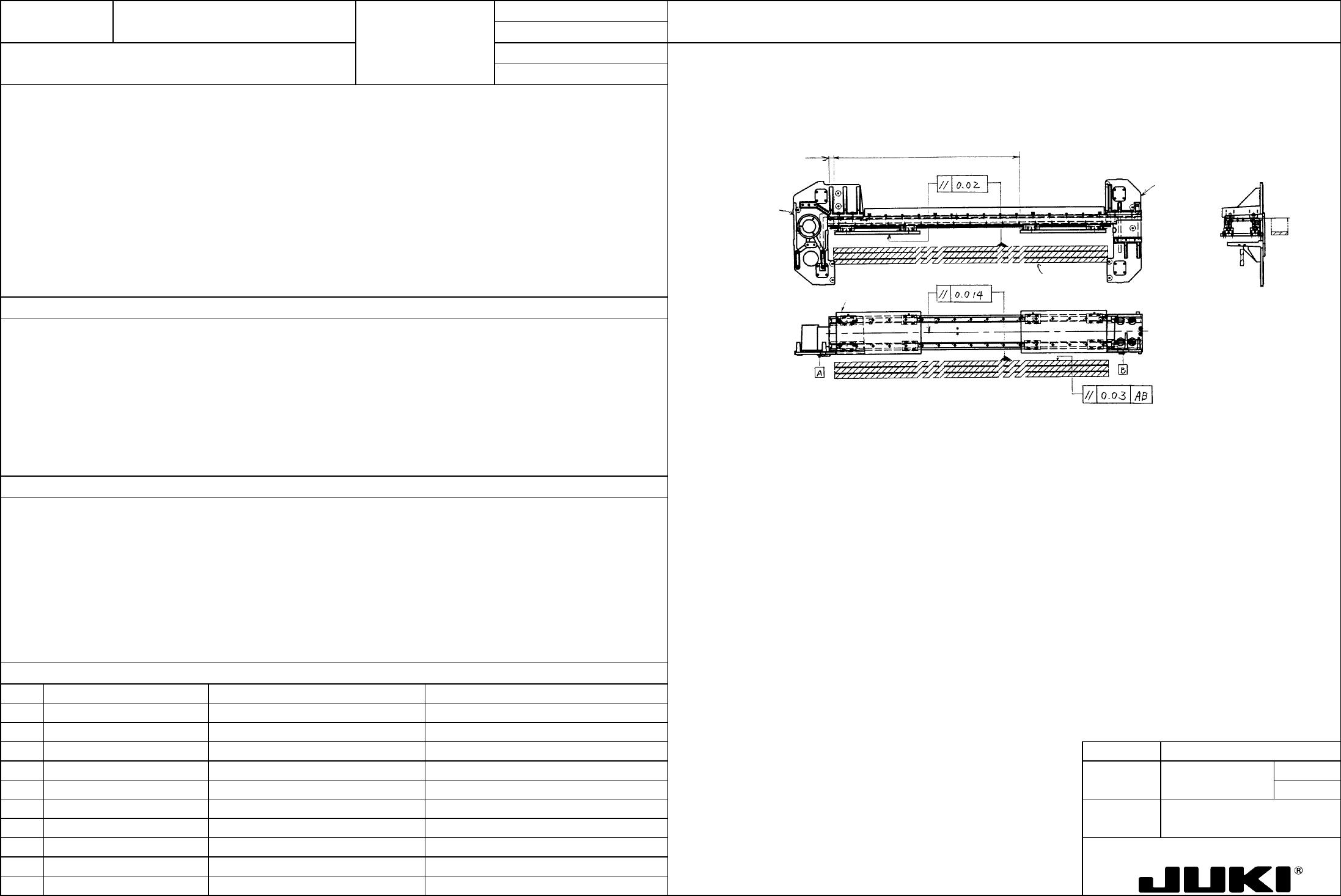
– Crosswise direction
– Head plate straightness in the crosswise direction: Within 20 um
– Head plate straightness in Z-direction: Within 14 um
Š
Z-direction
Head plate
(for jig)
I-shaped straightedge
X frame end R
X frame
end L
678 (stroke length)(from rail
end face)
Straightness in the crosswise direction affects placement accuracy (especially in Y-direction).
Straightness in Z-direction results in variations in height at pickup-and-placement.
Crosswise direction
Starting with a point 27 mm from the rail left end face, install a dial indicator to the head plate for jig (at around the
center of the head plate) and take a reading over a stroke of 678 mm. Report a substituted parallelism 0.02 with
respect to I-shaped straightedge.
Z-direction
– Degraded placement accuracy
Report a substituted parallelism of 0.014 over a stroke of 678 mm with respect to the I-shaped straightedge which has
been set to parallelism within 0.03 with reference to the surface of X frame end L/R on which the LM guide is
mounted.
– Pickup failure causing a chip to stand upright.
Adjustment procedure
– No adjustment can be made for the crosswise direction. For this, check X-axis frame, LM guide X, and back plate for
accuracy.
– For straightness in Z-direction, loosen four screws each that secure the X-axis frame to the X frame end L/R and adjust tilt
of the entire X-axis. If good straightness is not obtained even after this procedure, check LM guide X for installation and
straightness as a single unit.
FUNCTION NAME X-Axis Motion Load Function/Performance CHECK/ADJUSTMENT METHODS (REMEDIAL ACTION PROCEDURE)
ASSURED QUALITY Reliability
QUALITY CHARACTERISTICS (SPECIFICATION VALUES) CATEGORY Safety
Product Image
ROLE IN FUNCTION (MEANING OF SPECIFICATION VALUES)
POSSIBLE MALFUNCTIONS (CAUSED BY INCORRECT SPECIFICATION VALUES)
COMPONENTS
NO. Part No. Part Name Associated Quality Characteristics
1 E2402725000 X-axis frame
2 E2403725000 LM guide X
3 MODEL KE-750/760
4 UNIT X-Y Unit REF. NO.
5
NAME
XY-3
6 FUNCTION X-Axis Motion Load
7
NAME
8
9
10
QA Table
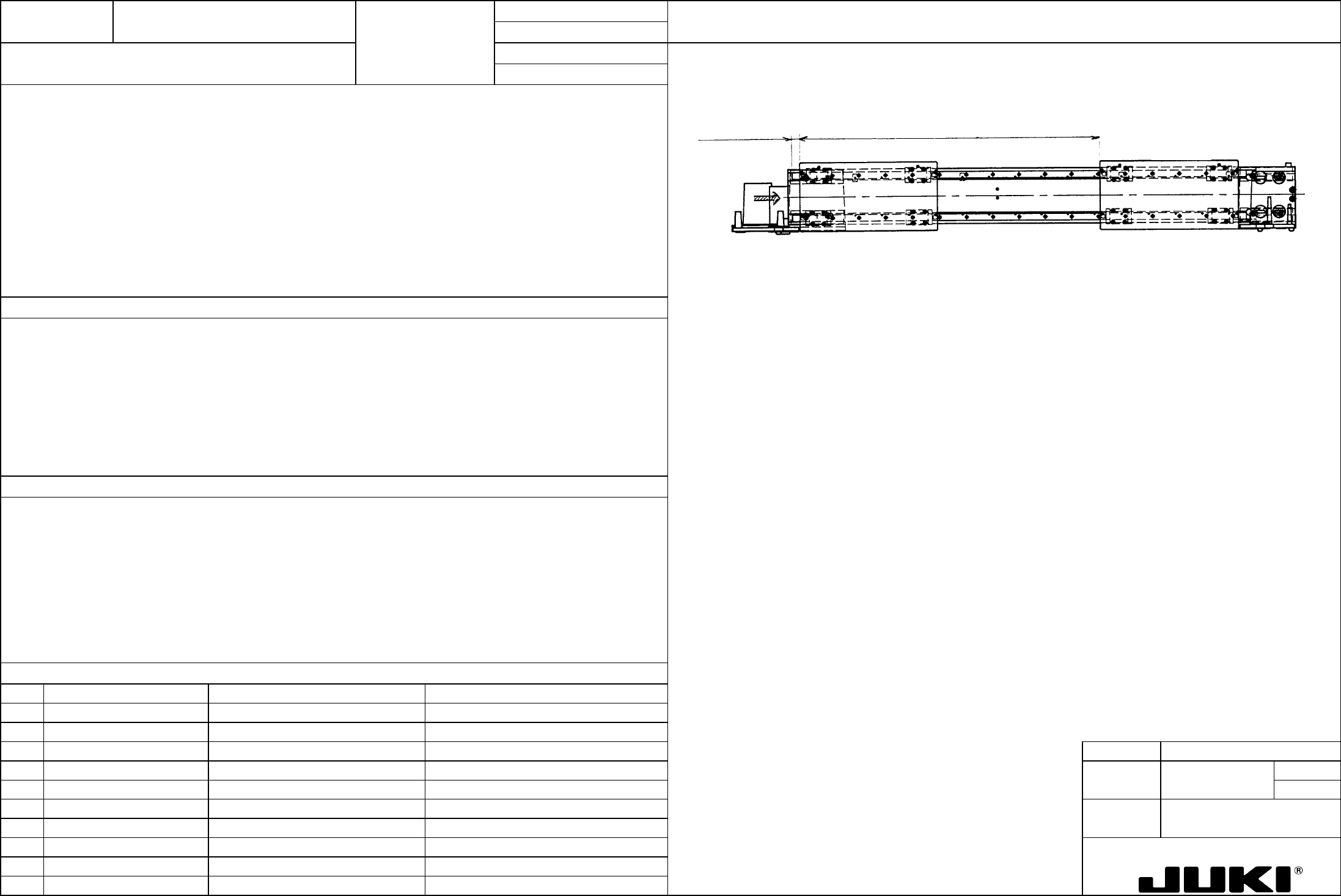
Head plate
P
678 (stroke range)
27 (from rail
end face)
– When head plate starts moving: 20 N or less
Variations in force during motion: 5 N or less
- No play, unusual noise, or oscillation are allowed while the LM block is moving.
– Using a spring balance, push the slide unit (jig plate) in P-direction and check at that time that the slide unit starts moving
with a force of 20 N or less. Variations in force after the unit has started moving should be 5 N or less over a stroke of
less than 678 mm.
– Holding the slide unit (jig plate) by hand, slide it over a stroke of less than 678 mm and make sure that the LM guide does
not generates noise or vibration (chattering).
– Concerned with the noise during machine operation
– Concerned with gain adjustment and settling time of motor
Remedial procedures
1. Loosen the screws that secure the jig plate and slide it to determine if the block has been pinched into position.
2. Check the two LM guides for parallelism and straightness.
3. If steps and 1 and 2 have been checked okay, the LM guide plate (ball itself, rolling contact surface) may be defective,
requiring replacement of the guide.
– Noise during operation:
Noise from the LM guide
Noise produced by motor oscillation
– Worn LM guide
– Degraded placement accuracy