KE-750_QA表.pdf - 第52页
FUNCTION NAME Straightness and Parallelism of LM Guide (Y) Function/Performance CHECK/ADJUSTMENT METHODS (REMEDIAL ACT ION PROC EDURE) ASSURED QUALITY Reliability QUALITY CHARACTERISTI CS (SPECIFIC ATION VALUES) CATEGORY…
FUNCTION NAME Parallelism in Y-Axis Frame L/R and LM Guide (Y) Function/Performance CHECK/ADJUSTMENT METHODS (REMEDIAL ACTION PROCEDURE)
ASSURED QUALITY Reliability
QUALITY CHARACTERISTICS (SPECIFICATION VALUES) CATEGORY Safety
Product Image
ROLE IN FUNCTION (MEANING OF SPECIFICATION VALUES)
POSSIBLE MALFUNCTIONS (CAUSED BY INCORRECT SPECIFICATION VALUES)
COMPONENTS
NO. Part No. Part Name Associated Quality Characteristics
1 E2301725000 Y-axis frame L
2 E2302725000 Y-axis frame R
3 E2303725000 LM guide (Y) MODEL KE-750/760
4 UNIT X-Y Unit REF. NO.
5
NAME
XY-4
6 FUNCTION Parallelism in Y-Axis Frame L/R
7
NAME and LM Guide (Y)
8
9
10
QA Table
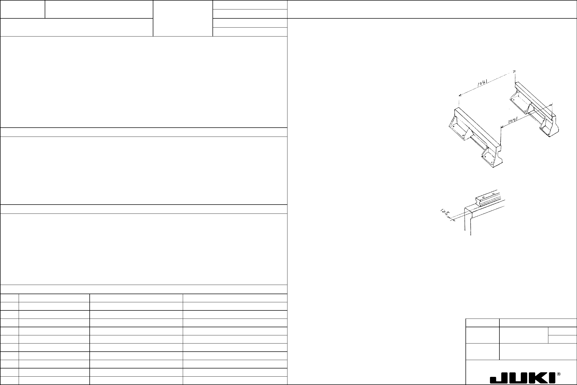
Parallelism between Y-axis frame L and R
Parallelism between Y-axis frame L and R:
The distance between the surfaces of Y-axis frame L and R to which magnescales are mounted is 1041 at their front end
and rear end.
[Check procedure]
(1) Using a scale, check that each of the dimensions
shown on the left measures 1041.
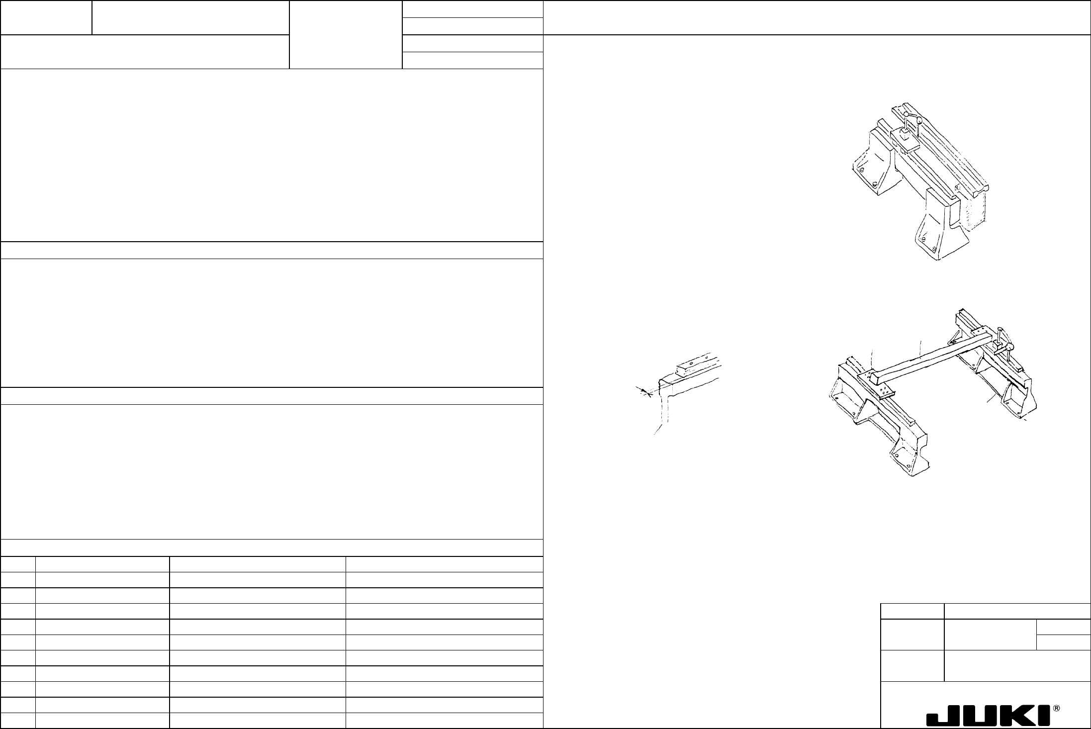
Parallelism between Y-axis frame and LM guide (Y):
The position of the Y-axis frame is basically
determined by the two each spring pins driven into
the base frame. If the specified dimension is not
obtained even though the Y-axis is pressed against
the spring pins, check the spring pin holes in the
base frame and the dimension between the Y-axis
surface which is pressed against the spring pins and
the magnescale mounting surface.
The distance between the Y-axis frame part to which magnescale is mounted and the end face of LM guide (Y) is 12.5.
[Adjustment procedure]
Loosen the set screws on the Y-axis frame and
adjust the position of the Y-axis frame.
Concerned with the level of accuracy maintained through Y-axis parallelism adjustment that greatly affects placement
accuracy.
Parallelism between the Y-axis frame and LM guide (Y)
[Check procedure]
Using vernier calipers, check that the dimension
between the surface of Y-axis frame L and R on
which magnescales are mounted and the LM guide
rail side face measures 12.5.
[Adjustment procedure]
Loosen the LM guide fixing screw and, pressing the
LM guide up against vernier calipers which has been
adjusted to 12.5 mm, tighten the fixing screw.
1. It becomes impossible to make a good adjustment of parallelism between the left and right LM guides of Y-axis.
2. When the X-axis frame assembly is mounted, the holes used for mounting the LM guide (Y) block are misaligned with
each other. If it is forcibly secured, the guide is loaded resulting in a noise or other abnormal symptom.
FUNCTION NAME Straightness and Parallelism of LM Guide (Y) Function/Performance CHECK/ADJUSTMENT METHODS (REMEDIAL ACTION PROCEDURE)
ASSURED QUALITY Reliability
QUALITY CHARACTERISTICS (SPECIFICATION VALUES) CATEGORY Safety
Product Image
ROLE IN FUNCTION (MEANING OF SPECIFICATION VALUES)
POSSIBLE MALFUNCTIONS (CAUSED BY INCORRECT SPECIFICATION VALUES)
COMPONENTS
NO. Part No. Part Name Associated Quality Characteristics
1 E2303725000 LM guide (Y)
2 E2301725000 Y-axis frame L
3 E2302725000 Y-axis frame R DEL KE-750/760 MO
4 UNIT X-Y Unit REF. NO.
5
NAME
XY-5
6 FUNCTION Straightness and Parallelism of
7
NAME LM Guide (Y)
8
9
10
QA Table
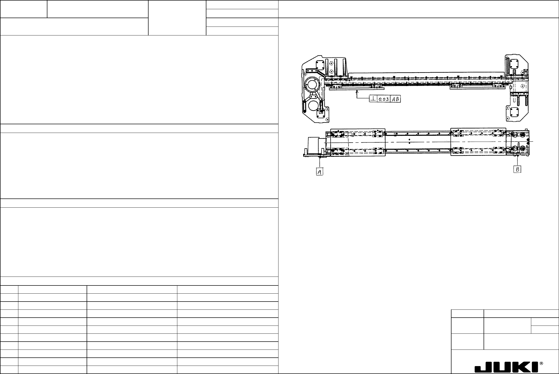
Straightness
Straightness of LM guide (Y): 20 um or less in each rail
Jig
X Axis Frame R
X Frame End L
[Check procedure]
Parallelism between left and right LM guides (Y): 20 um or less
(1) Place two base bridges on the top surface of base
frame and mount a jig on which to install the I-shaped
straightedge. (Place the I-shaped straightedge on
the transport rails if the machine is equipped with a
PWB transport unit.)
(2) Set a dial indicator on the LM guide (Y) block and
adjust I-shaped straightedge to "0" on both ends of the
guide.
(3) Check that straightness is 20 um or less over the
entire stroke of the LM guide.
[Adjustment procedure]
(1) Check that the distance between the Y-axis frame
surface on which magnescale is mounted and the LM
guide rail side face measures 12.5 mm.
– Concerned with critical positional deviations (especially in X-direction) in pickup and placement, it affects placement
accuracy.
(2) Near the portion at which straightness falls outside the
specified range, loosen the bolt that secures the LM
guide and, adjusting the rail position, tighten the bolt
again.
- Affects smoothness of the X-axis motion in Y-direction.
– Degraded placement accuracy
– Noise during motion in Y-direction
12.5
– Reduced LM guide durability
Parallelism
[Check procedure]
(1) Mount the X-axis frame jig (or X-axis frame assembly)
on Y-axis and fix the left LM guide block to frame end
L.
(2) Temporarily secure the right LM guide block to frame end R, set a dial indicator to frame end R, and apply the dial
indicator to the rail side face of LM guide.
(3) Move frame end L and check that parallelism is 20 um or less over the entire stroke of LM guide.
[Adjustment procedure]
(1) Loosen the screw that secures Y-axis frame R to the base frame. Move the X-axis frame jig (or X-axis frame
assembly) on the frame end L side and, adjusting the position of Y-axis frame R, make an adjustment for parallel
alignment.
(2) After the adjustment has been made, tighten the Y-axis frame R set screw.
FUNCTION NAME Squareness of Head Plate (Jig) Function/Performance CHECK/ADJUSTMENT METHODS (REMEDIAL ACTION PROCEDURE)
ASSURED QUALITY Reliability
QUALITY CHARACTERISTICS (SPECIFICATION VALUES) CATEGORY Safety
Product Image
ROLE IN FUNCTION (MEANING OF SPECIFICATION VALUES)
POSSIBLE MALFUNCTIONS (CAUSED BY INCORRECT SPECIFICATION VALUES)
COMPONENTS
NO. Part No. Part Name Associated Quality Characteristics
1 E2402725000 X-axis frame
2 E2405725000 X frame end L
3 E2406725000 X frame end R MODEL KE-750/760
4 E2427725000 X end adjust shim A UNIT X-Y Unit REF. NO.
5 E2428725000 X end adjust shim B
NAME
XY-6
6 E2429725000 X end adjust shim C FUNCTION Squareness of Head Plate (Jig)
7
NAME
8
9
10
QA Table
X frame end L 7/ X frame end R
Squareness of the head plate with respect to the reference surface of X frame end L/R: 0.03 or less
Important to ensure squareness between the PWB transport surface and head.
Using a square master, measure squareness of the head plate (jig) with reference to the X frame end L/R surface on
which LM block is mounted. At this time, the head plate (jig) shall be located at almost the center of the X-axis frame.
Adjustment procedure:
To arrive at the specified squareness, select the following shims to make up a combination and place them in the coupling
between the X-axis frame and X frame end L/R:
– Degraded placement accuracy
X end adjust shim A (t 0.1)
– Pickup failure
X end adjust shim B (t 0.05)
X end adjust shim C (t 0.03)