KE-750_QA表.pdf - 第54页
FUNCTION NAME Gap Between the Magnescale A ffixing Function/Performance CHECK/ADJUSTMENT METHODS (REMEDIAL ACT ION PROCEDURE) Position and Head ASSURED QUALITY Reliability QUALITY CHARACTERISTI CS (SPECIFIC ATION VALUES)…
FUNCTION NAME Squareness of Head Plate (Jig) Function/Performance CHECK/ADJUSTMENT METHODS (REMEDIAL ACTION PROCEDURE)
ASSURED QUALITY Reliability
QUALITY CHARACTERISTICS (SPECIFICATION VALUES) CATEGORY Safety
Product Image
ROLE IN FUNCTION (MEANING OF SPECIFICATION VALUES)
POSSIBLE MALFUNCTIONS (CAUSED BY INCORRECT SPECIFICATION VALUES)
COMPONENTS
NO. Part No. Part Name Associated Quality Characteristics
1 E2402725000 X-axis frame
2 E2405725000 X frame end L
3 E2406725000 X frame end R MODEL KE-750/760
4 E2427725000 X end adjust shim A UNIT X-Y Unit REF. NO.
5 E2428725000 X end adjust shim B
NAME
XY-6
6 E2429725000 X end adjust shim C FUNCTION Squareness of Head Plate (Jig)
7
NAME
8
9
10
QA Table
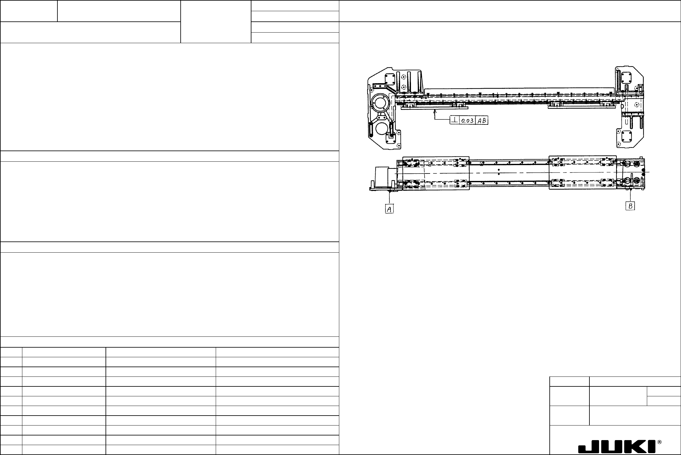
X frame end L 7/ X frame end R
Squareness of the head plate with respect to the reference surface of X frame end L/R: 0.03 or less
Important to ensure squareness between the PWB transport surface and head.
Using a square master, measure squareness of the head plate (jig) with reference to the X frame end L/R surface on
which LM block is mounted. At this time, the head plate (jig) shall be located at almost the center of the X-axis frame.
Adjustment procedure:
To arrive at the specified squareness, select the following shims to make up a combination and place them in the coupling
between the X-axis frame and X frame end L/R:
– Degraded placement accuracy
X end adjust shim A (t 0.1)
– Pickup failure
X end adjust shim B (t 0.05)
X end adjust shim C (t 0.03)
FUNCTION NAME Gap Between the Magnescale Affixing Function/Performance CHECK/ADJUSTMENT METHODS (REMEDIAL ACTION PROCEDURE)
Position and Head
ASSURED QUALITY Reliability
QUALITY CHARACTERISTICS (SPECIFICATION VALUES) CATEGORY Safety
Product Image
ROLE IN FUNCTION (MEANING OF SPECIFICATION VALUES)
POSSIBLE MALFUNCTIONS (CAUSED BY INCORRECT SPECIFICATION VALUES)
COMPONENTS
NO. Part No. Part Name Associated Quality Characteristics
1 E9606715000 Magnescale
2 E9609721000 Magnescale
3 E9608721000 Magnescale head MODEL KE-750/760
4 E2402725000 X-axis frame UNIT X-Y Unit REF. NO.
5 E2405725000 X frame end L
NAME
XY-7
6 E2415725000 X-MSC bracket FUNCTION Gap Between the Magnescale
7 E2301725000 Y-axis frame L
NAME Affixing Position and Head
8 E2302725000 Y-axis frame R
9 E2319725000 Y-MSC bracket L
10 E2320725000 Y-MSC bracket L
QA Table
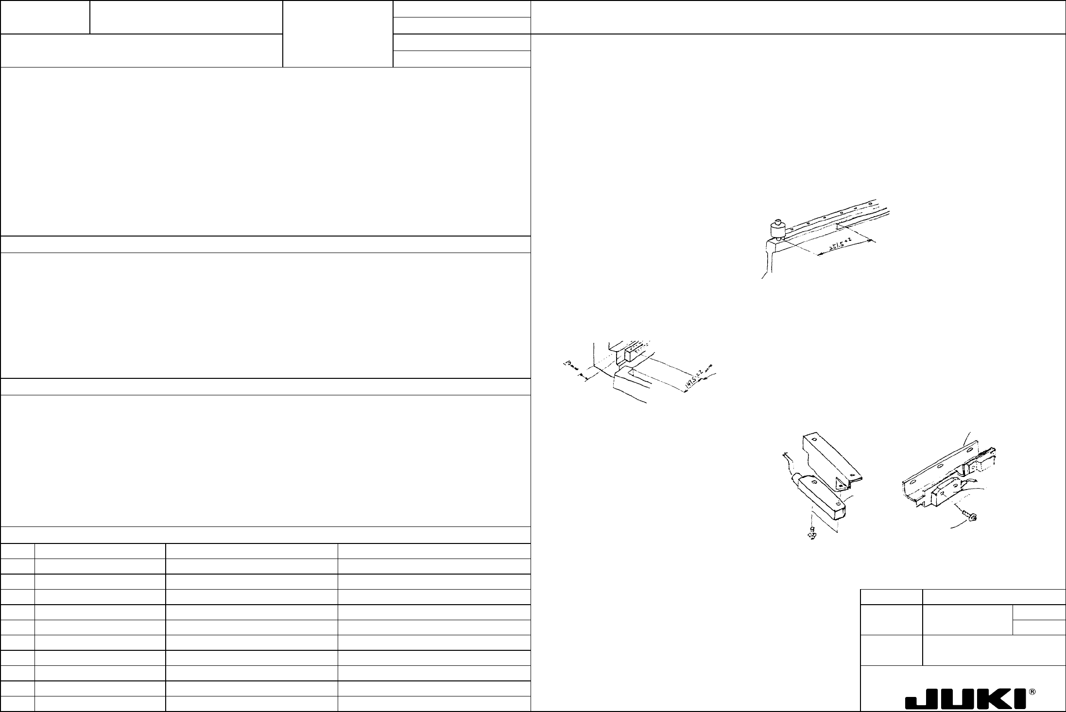
Affixing Y-axis magnescale:
Magnescale affixing position
(1) Wipe the magnescale cover clean of dirt with a cloth dampened with alcohol.
– Y-axis:
(2) Wipe the magnet surface of the magnescale clean with a clean soft cloth.
251.5 ±2 mm from the LM guide front end face.
(3) Using double-sided adhesive tape, affix the cover to the magnescale.
Affix magnescale along the LM guide mounting surface.
(4) Affix the serial no. and rating nameplate.
– X-axis:
(5) Wipe clean the Y-axis frame surface with alcohol and affix the magnescale to the specified position.
147.5 ±2 mm from the X frame end L surface on which stopper is mounted.
* Do not allow magnescales to be in contact with each other.
10 mm from the X-axis frame rear surface.
* Keep a magnetized screwdriver and any other body away from the magnescales.
Head cap 1.5mm
- Distance between the X frame end
L stopper mounting surface and
magnescale end face: 147.5 ±2
mm
- 10 ±2 mm from the X-axis frame
rear surface
(Affix along the marking-off line.)
Loosen the M4x20 set screw,
insert two furnished spacers
into the space between the
magnescale and head, and
then tighten the set screw to the
specified torque (0.9 Nm).
Check that the magnescale is
not in contact with the head
over the entire stroke.
Magnescale
end face
(See the Y-axis magnescale affixing procedure.)
A
ffixing the X-axis magnescale:
251.5 ±2 mm from the LM
guide front end face.
Important in accurately providing feedback control of the X- and Y-axis.
– Poor accuracy in X/Y stopping position
Magnescale
head
Tightening torque: 0.9Nm
X-MSC bracket
Magnescale
head
Y-MSC bracket
Magnescale detection head
gap adjustment (X/Y-axis)
A
djustment value: 1.5 mm
(furnished spacers used)
*Wipe the surface clean of dirt
with alcohol.
– Degraded placement accuracy
– Defective sensor
FUNCTION NAME X/Y Squareness and Home Position Sensor Function/Performance CHECK/ADJUSTMENT METHODS (REMEDIAL ACTION PROCEDURE)
Position
ASSURED QUALITY Reliability
QUALITY CHARACTERISTICS (SPECIFICATION VALUES) CATEGORY Safety
Product Image
ROLE IN FUNCTION (MEANING OF SPECIFICATION VALUES)
POSSIBLE MALFUNCTIONS (CAUSED BY INCORRECT SPECIFICATION VALUES)
COMPONENTS
NO. Part No. Part Name Associated Quality Characteristics
1
2
3 MODEL KE-750/760
4 UNIT X-Y Unit REF. NO.
5
NAME
XY-8
6 FUNCTION X/Y Squareness and Home
7
NAME Position Sensor Position 1/2
8
9
10
QA Table
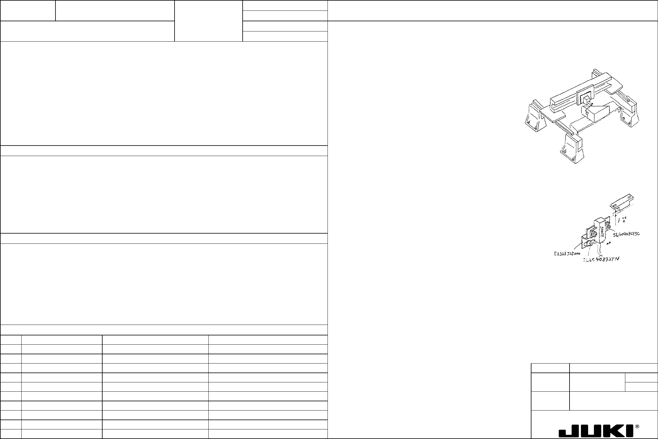
Check procedure:
– X/Y squareness: 0.03/500 mm (square side length)
X/Y squareness
– Y-axis home position sensor activation: The left and eight sensors must be activated at the same time.
– Mount two base bridges at the front and rear on the base frame,
place a square base on it, and then place a square on the base.
– Gap between the home position sensors: 1 +2/0 mm
– Align one side of the square in parallel with the sliding direction
of Y-axis and check the X-axis for squareness with respect to the
other side of the square (by using a dial indicator).
Y-axis home position sensor position
– Turn on the system and, with the servo in free state, remove the
Y belt support from X frame end L/R and check for clearance.
– Move the X-axis frame assembly from the rear to the front and
make sure that the left and right home position sensors are
activated to light up their LEDs at the same time. (For details,
see p. 2/2.)
Adjustment procedure
– Directly affects inaccurate squareness in placement accuracy.
X/Y squareness
- Misaligned left and right sensors cause the X-axis binds during sliding, applying an excessive load on the LM guide and
other mechanism.
– Loosen the screw that secures the X frame end L/R to LM guide
and move the X-axis frame assembly to adjust squareness so
that it is square to 0.03 or less with respect to one side of the
square.
– After the adjustment has been completed, tighten the X-axis
frame assembly set screw to the specified torque (9 Nm).
Y-axis home position sensor position
– To adjust gap, loosen SL4040801SC that secures the sensor to
its bracket and move the sensor up or down as necessary.
– To adjust for simultaneous activation of right and left sensors,
loosen SL6040892TN that secures the bracket and move the
bracket to the right or left as necessary. (For details, see p. 2/2.)
– Degraded placement accuracy
– Noise from LM guide
– Damaged LM guide
– Damaged home position sensor